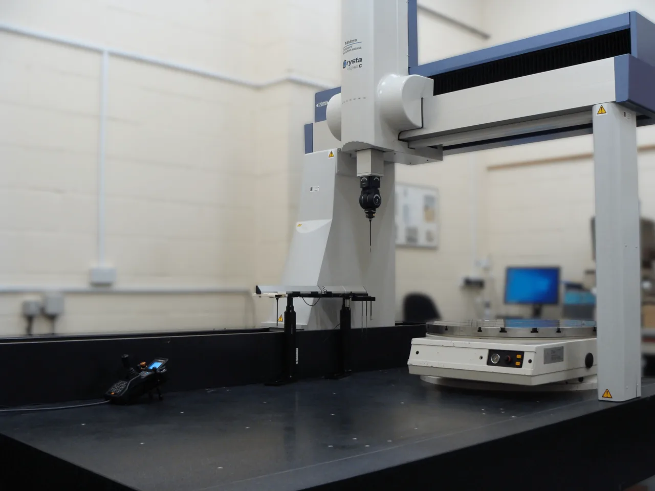
A scanning probe is the analog sensing head that lets a coordinate measuring machine slide its stylus tip along a surface and record deflection continuously, capturing hundreds to thousands of measured points per second instead of one point per touch. It is the tool for form evaluation: roundness, cylindricity, profile of a blade or cam, and full-surface comparison against CAD on machined, molded, and printed parts.
Specifying one means deciding the deflection range and measuring force that match the parts, the point rate the smallest feature requires, and the scanning-error class the tolerances demand. This page decodes those lines, explains the spring-and-sensor mechanism inside the head, and maps the boundary where discrete touch-trigger probing gives way to continuous scanning.
On the same CMM, the touch-trigger probe remains the tool for feature location: a bolt-circle of hole positions takes ten touches and finishes faster than a scan. The scanning probe earns its mount when the drawing says roundness, profile, or surface continuity. Around both sit the non-contact options, a structured light scanner or a vision measuring machine for edges and flexible parts, and the shop-floor staples from a height gauge to a roundness tester in dedicated stations; each has a duty it wins.
A scanning probe turns surface following into data density: the stylus rides the part and the head reports deflection continuously, so form is measured rather than inferred from a few points. This page gives the compliant-suspension mechanism, the ISO 10360-4 scanning-error vocabulary, the throughput economics against touch-trigger probing, and the RFQ lines that make the purchase auditable from acceptance test to daily reference scan.
Chapter 1 / 06
What Is a Scanning Probe
Physically, a scanning probe is a stylus carried on a compliant suspension whose position is measured, not merely switched. As the CMM moves the tip along the surface, the suspension deflects by microns; sensors inside the head, optical scales or differential transformers in modern designs, report deflection in two or three axes at high rate, and the controller combines machine axes and probe deflection into a continuous stream of surface coordinates. The machine no longer stops at each point; it follows the contour with the probe riding in its working deflection band.
The selection question arises when drawings stop asking where features are and start asking what shape they are. Roundness of a bearing journal, cylindricity of a bore, profile of an airfoil section, flatness of a sealing face across its full area, and crown or twist on gear teeth are form statements. Discrete points sample them; scanning measures them. A 4-point circle cannot see lobing between the points, and a 25-point circle aliases on waviness, while a 2,000-point scan traces the actual contour including its harmonics.
What is actually being decided at purchase is the error budget for form work. Scanning contributes scanning error, the residual form and size error the probing system adds under follow-mode conditions, measured by standardized tests; the machine contributes its length errors on the path; thermal drift and stylus dynamics add time- and speed-dependent terms. As with discrete probing, the process should consume a minority share of the tolerance, so the scanning-error class is chosen from the tightest form tolerance on the part list, not from the brochure's best figure.
The economics are throughput economics. A form feature scanned in one pass replaces dozens of discrete touches; a full part contour compared to CAD replaces an hour of point programming with a boundary definition. Measurement rooms that moved from touch-trigger-only to scanning report cycle-time cuts on form-heavy parts and, more quietly, a drop in programming time per new part, because scanning paths are defined by boundaries and sections rather than by point-by-point geometry. The same data density changes what quality engineers can ask: statistical form trends across a production run, harmonic analysis of bore lobing, and wear signatures on tooling all become ordinary queries instead of special studies.
Where scanning sits in the inspection room
A form-measurement capability is a portfolio decision, and the scanning probe is its center of gravity, not its whole surface. The machine under the head positions it: a CMM's axes read their position from a linear encoder per axis, and the scanning result is only as good as those scales and their error mapping, which is why head upgrades ride on machine verification, not beside it. Around the room, bench instruments keep their posts: a caliper micrometer at the workstation for quick diameters, a thickness gauge for wall checks, an optical comparator for shadow-outline checks of small stamps. A dedicated contour measuring machine still earns bench space for profile tolerances on seals and cams at production volume, and a surface roughness tester owns the finish parameters, Ra and Rz, which are surface-integral statements no stylus contour scan replaces. The scanning CMM ties these together as the flexible center; it does not retire them.
Non-contact and large-scale neighbors complete the map. A 3D scanner captures whole surfaces in minutes for reverse engineering and first-article comparison where sub-ten-micron accuracy suffices; a vision measuring machine with an industrial camera reads edges and small 2D geometry without touching the part; a laser displacement sensor profiles recesses and soft surfaces at high speed. At the far size end, a laser tracker carries the same traceability to airframe and machine-tool assemblies meters away. The scanning probe's unique claim inside this field is contact-class accuracy on hard surfaces with full form semantics, the combination none of the others delivers.
Two name-alikes deserve a paragraph in the RFQ so they never arrive in the wrong crate. A proximity probe in rotating-machinery monitoring is an eddy-current displacement sensor watching shaft motion, a continuous analog instrument like the scanning head but built for kilohertz bandwidth and bearing clearances, not coordinate metrology. A load cell measures force, full stop; its calibration chain shares the force ledger with the scanning head's milli-newton spring force but nothing else. Naming the standard and the artifact in the purchase order, rather than the generic word probe, keeps the shelves stocked with what the form-measurement plan actually needs.
Chapter 2 / 06
Working Principle and Probe Types
The compliant suspension
The heart of the head is a spring parallelogram or membrane arrangement that holds the stylus with defined stiffness in each axis, paired with a displacement sensor per axis. Stiffness sets measuring force: the suspension pushes the tip against the surface with a force proportional to deflection, commonly quoted in the range of tens to a few hundred millinewtons at nominal deflection, gentler than most touch-trigger trigger forces by design. The controller drives the machine to hold deflection inside a working window; the surface contour becomes the deflection signal, and the servo closes the loop thousands of times per second.
Two engineering numbers follow. Deflection range, how far the suspension can travel while staying linear, sets crash margin and the ability to bridge small gaps; typical working ranges run a fraction of a millimeter with full-linear behavior in a narrower central band. Natural frequency decides how fast the head can follow curvature changes without lag; at scanning speeds of fractions of a millimeter per second to a few millimeters per second, modern heads track sub-micron features, and the limitation on feature fidelity is more often stylus bending and machine dynamics than the suspension itself.
The deflection readout is what makes the head a measuring instrument rather than a switch. Each axis's sensor pair resolves sub-micron motion across the working band, with linearity and zero stability quoted in the head specification; the controller's job is to keep the suspension near center so the readout stays in its linear heart, and to timestamp deflection against machine position tightly enough that point coordinates do not smear along the path. That fusion, scales plus deflection plus time, is why a scanning head's price sits where it does: it is three short-range metrology instruments and their clock, packaged at a stylus.
Passive, active, and spindle-integrated designs
Passive scanning heads hold the stylus on the spring suspension and read deflection; the machine's drives do the following. They are simple, robust, and the standard fit on mid-range CMMs. Active scanning heads add a small actuator in the head so the suspension itself re-centers as the contour changes, extending follow speed and accuracy on tight curvature and on machines whose drives are the limiting element. Integrated-spindle designs, most visibly five-axis scanning heads, rotate and swivel the head while the machine moves slowly, keeping the stylus normal to the surface and the dynamics benign; the same hardware then also serves discrete touch-trigger measurement by switching modes.
The choice among the three is a machine-matching exercise more than a head-quality ranking. A passive head outruns a slow machine's ability to follow contours, and its residual error then reflects the drives, not the suspension; an active head on the same machine buys back margin by re-centering internally. Five-axis scanning inverts the whole geometry: the head's two fast rotary axes carry the dynamics, the machine's three linear axes creep, and the result is both faster scanning and gentler machine motion on complex parts, at the price of a more elaborate qualification model and a head whose service is a specialist affair. Match the head generation to the machine's controller generation in the RFQ; a flagship head on a legacy controller delivers flagship invoices with legacy performance.
Point rate lines the catalog pages: hundreds to a few thousand points per second on mainstream heads, higher on flagship systems, with effective spatial resolution set by rate divided by path speed. At 1 mm/s and 500 points per second, points land every 2 micrometers, far finer than any form tolerance of interest; the practical reason for higher rates is noise averaging and faster scans, not finer spacing. Rate also bounds area work: rastering a 100 by 100 mm face at 1 mm line pitch and 2 mm/s spends most of a shift, which is why flatness over areas is often better served by a few strategic lines plus a fitted plane than by a heroic full-field raster.
Scan modes in practice
Circle and cylinder scans on bores and journals; open and closed section scans along CAD curves for profiles; area scans rastering a face for flatness; boundary scans that follow a part edge; and touch-scan hybrids that touch an edge to find it, then scan along it. Each mode has its qualification: scanning heads are calibrated for deflection gain and stylus radius in place, on a calibrated sphere, with the calibration validated by the standardized scanning tests before the head is trusted for release measurements.
Filtering and evaluation policy is part of the mode, not an afterthought. Form numbers depend on the filter band applied to the point cloud: a roundness value evaluated with a steep low-pass filter reads smaller lobes out than the same scan with a wider band, which is why GPS profile standards fix the filter and why the RFQ should name the evaluation framework the reports must follow. Sample count harmonics matter too: a 360-point circle resolves lobing up to a stated harmonic order, and scanning's thousands of points push that ceiling far past what any discrete program could afford. The discipline is to fix filter and speed once per feature family, write both into the program template, and never let operators improvise them per shift.
Chapter 3 / 06
Construction, Materials, and Duty Boundaries
Mechanical build
Head bodies are stainless with polymer or ceramic isolation; suspensions are hardened steel or beryllium-copper flexures; styluses follow the same discipline as touch-trigger work: carbide or ceramic shafts, ruby or zirconia balls, and joint-count discipline, because every added joint degrades the deflection model. Scanning amplifies stylus choice more than touch probing does: shaft bending under measuring force is a systematic term the calibration absorbs only for the qualified direction set, so long, star, and cranked styluses carry wider scanning-error values than the short straight stylus the datasheet headline quotes. Ball selection is part of the model too: ruby wears and picks up adhesive on aluminum, zirconia suits that duty, and a scarred ball drags a one-sided artifact through every scan it touches.
Sensing and electronics
Deflection sensors are optical scale strips or LVDT-family transformers per axis, sampled and filtered in head electronics, then fused with machine scales in the controller. Head temperature coefficients matter at the sub-micron level: serious scanning assumes the 20 deg C room, and mid-range heads quote internal compensation for a stated band. Cabling runs through the quill to the controller interface; motorized change racks treat the scanning head as one position among several, alongside a touch-trigger probe, so one machine carries both sensing modes and changes between them inside a program.
Duty boundaries
Scanning stops being the right tool at three edges. Very small features: a stylus ball of 0.3 mm cannot scan a 0.5 mm radius fillet; optical methods such as a vision measuring machine or a confocal sensor take over. Very soft or flexible surfaces: even tens of millinewtons deflect foils and elastomers; non-contact scanning, structured light scanner systems or chromatic probes, measures them without loading. Deep recesses with sharp direction changes: stylus reach plus suspension dynamics fight the geometry, and a shorter stylus with a head re-orientation, or a discrete probe taking a few points, is the honest answer. Within its envelope, the scanning probe is unmatched: hard surfaces, form tolerances from tenths of microns upward, and part sizes up to the machine's volume.
Sample preparation is a boundary buyers forget until the first shift. Scanning rides the surface: coolant residue, chips, and lint become apparent contour features at micron scale, so parts need a wash and blow-off discipline that touch probing tolerated sloppily. Fixturing loads matter at the same scale: a part clamped hard enough to bow by a micron measures its clamp, not its geometry, and thin-walled rings want three-point support on vee-blocks or an expanding mandrel instead. The scanning program's fixturing sheet is thus a metrology document; write it, version it, and keep it with the program the way tool lists ride with machining programs.
Chapter 4 / 06
Key Specification Parameters
The decode table lists the lines that decide fitness for a form-measurement duty, with the catalog spread and the meaning of each at the part.
Datasheet line
Mainstream passive
Active / 5-axis class
What it decides
Scanning error on calibrated circle
0.8 to 2.5 um
0.3 to 1.0 um
Form-and-size residual added in follow mode
Single-point repeatability class
0.3 to 1.0 um
0.15 to 0.5 um
Noise floor for fine contour detail
Measuring force at nominal deflection
0.05 to 0.30 N
0.01 to 0.15 N, often selectable
Part loading on thin walls; stylus bending
Deflection range, x/y/z
+/-0.5 to +/-1.0 mm typ.
+/-0.5 mm class with re-centering
Follow window, crash margin, gap crossing
Point rate
100 to 1,000 pts/s
500 to 5,000+ pts/s
Scan speed and noise averaging
Max stylus length (rated)
50 to 100 mm
100 to 250 mm with care
Reach before bending dominates the budget
Touch-trigger mode
most heads switchable; separate head still faster for volume point-taking
Read the scanning-error line against the test that produced it. The standardized family is the ISO 10360-4 scanning probing test, a scan of a calibrated sphere or ring with the residual form and size compared against the certificate, and vendor datasheets quote their scanning error under stated conditions of speed and stylus. When comparing quotations, normalize: same stylus length, same scan speed, same artifact; a headline quoted at low speed with a short stylus will not transfer to a 100 mm reach running at production speed.
Decode the force and deflection lines as a pair. Measuring force times stylus length is a bending moment the calibration absorbs only for the qualified direction set; a 0.2 N force on a 100 mm stylus deflects the shaft by microns, and off-vector scanning directions convert that bend into apparent form error. Deflection range sets the head's tolerance of the unexpected: a fillet radius tighter than planned, a part seated a few tenths high, or a gap crossing each spend range margin; a head that saturates its range mid-scan drops points exactly where curvature is most interesting. Selective-force heads let one machine run stiff styli on ground steel in the morning and fine styluses on thin-wall parts in the afternoon without swapping hardware.
The second table decodes the acceptance-test vocabulary to write into the PO.
Test
Basis
Typical acceptance
Scanning probing error, form+size
ISO 10360-4 sphere or ring scan, 4 or more positions
Work the decision in this order; each step fixes a number or eliminates an option.
List the form tolerances on the part mix, with their sizes and materials; the tightest one sets the scanning-error class target after the 10 to 25 percent process-share budget is applied.
Inventory access geometry: bore depths, profile curvatures, and section heights set stylus length, ball diameter, and whether head articulation is needed to keep the stylus near-normal.
Match the machine: a passive head on slow drives is a balanced mid-market answer; active or five-axis scanning pays on high-curvature work and on throughput-critical cells.
Decide the dual-mode question: keep a touch-trigger head in the rack for volume point work, or accept mode-switching on one head; quantify change overhead per program.
Fix the measuring force policy: select lower forces for thin walls and fine styluses; confirm the deflection range covers the part's expected form amplitude.
Specify the change system capacity: head positions, stylus positions, and change repeatability, so unattended night programs never wait on a manual swap.
Verify the software chain: scanning path planning, CAD import, and evaluation of form per the drawing's framework (GPS profile requirements), because the head is only as useful as the evaluation software behind it.
Price the system: head, rack, stylus set, qualification artifacts, software modules, and the acceptance test on your machine, over the planned life.
The cost table shows the honest structure of an upgrade decision on an existing mid-size CMM.
Element
Touch-trigger only (today)
Add passive scanning
Add 5-axis scanning
Head and interface, index
100
180 to 250
300 to 450
Rack and qualification set
included
+40 to 80
+60 to 120
Software modules
base
scan evaluation
scan + 5-axis path
Cycle time on form-heavy part
baseline
30 to 60% faster
40 to 75% faster
Programming time per new part
baseline
lower
lowest
What to write in the RFQ, verbatim:
Part spectrum: materials, tightest form tolerance, feature list (bores, profiles, faces), sizes, and access geometry.
Performance: ISO 10360-4 scanning error and ISO 10360-5 probing error with your stylus stack at working length, at production scan speed; acceptance on your machine.
Head specification: measuring force and its adjustability, deflection range per axis, point rate, max stylus length and ball set.
Software: scanning path planning, CAD formats, form evaluation per GPS, and reporting templates.
Environment: room class assumed by the quoted numbers; compensation band.
Acceptance: ISO 10360-4 and 10360-5 tests witnessed, artifacts and certificates delivered, training for scanning path programming included.
Two clauses settle the arguments that otherwise surface in year two. The stylus-annex clause: quote the scanning-error class at the stylus lengths you will actually use, with the stylus set priced as a line item, because the gap between a short-stylus headline and a long-stylus working value is where disappointed expectations live. The arbitration clause: name the reference instrument, a roundness tester or a higher-class CMM, that settles disputes on scanning results for your tightest feature, and budget for a periodic cross-check campaign against it; a measured agreement ratio is what lets a quality department defend scanning numbers to a customer's auditor without a demonstration every time.
Borderline duties deserve a named arbiter. Roundness on a shaft journal can be measured on the CMM with a scanning probe or on a dedicated roundness tester; the CMM wins on flexibility and batch integration, the dedicated instrument on spindle-class repeatability and vibration immunity. Small plastic and rubber parts sit at the other border, where contact scanning bends the part and optical methods win. Write these border cases into the RFQ's part spectrum so the vendor answers them with data instead of the sales answer.
Chapter 6 / 06
Field Practice: Qualification, Standards, and Maintenance
Qualification discipline
Scanning heads qualify in place: a calibrated sphere, a defined scan set, and a solve for deflection gain and effective stylus radius, repeated after every stylus change and any event that stresses the suspension. Validate with the standardized scanning test after qualification and log the residual; a head that re-qualifies but no longer reproduces its certified scanning error is signalling stylus or suspension damage, not calibration drift. Keep the qualification sphere mounted and clean, because the entire form-traceability chain hangs from that one artifact between annual verifications.
Failure modes and signatures
The recurring failures are legible in scan data. Directional asymmetry in circle scans points to stylus bend or a suspension zero offset; run the calibration and see which term moves. High-frequency noise that grows with scan speed is dynamics: slow the scan, shorten the stylus, or re-orient the head. Step errors at scan direction reversals indicate backlash-class effects in head re-centering or machine drives; report them rather than filtering them out, because they mask real part edges. Surface contamination on the ball, adhesive pickup from gummy parts, flats the contour subtly; clean ruby balls with solvent and inspect under magnification weekly in production duty. Crashes that over-travel the suspension are the major event: the head may survive with a shifted zero, but only the acceptance test tells.
Maintenance cadence
Daily: stylus and ball cleanliness, fixture and part seating checks, a one-minute reference scan on the qualification sphere compared against yesterday. Weekly: stylus joint torque inspection, rack function, cable strain reliefs at the quill. Annual: full ISO 10360 reverification including the scanning test, suspension zero verification, and electronics self-test; after any collision, relocation, or controller update, the same suite runs early rather than on schedule. Log everything against the artifact certificates; when an audit or a customer dispute asks how a form number was trustworthy on a given date, the log is the answer.
Operator craft decides more of scanning quality than buyers expect. Scan direction relative to machine axes, approach ramps into the surface, and retrace strategy over burrs are technique items with visible effects on residuals; a one-day vendor training plus a written local practice sheet, scan speeds, filters, and fixture rules per feature family, converts a head purchase into a measurement capability. The best operators treat a scan program like a machining program: proven once, locked, and changed only through the document trail, because an improvised scan speed or a swapped stylus without re-qualification is the scanning-room equivalent of a tool change without an offset update.
The room remains half the budget. Scanning headline numbers assume thermal stability at 20 deg C; a room that cycles two kelvins through a shift will show it in scan-to-scan size drift long before it shows in touch-trigger points. Part soak discipline, temperature logging, and honest correction factors keep the scanning investment honest; conversely, a stable room is the cheapest accuracy upgrade any CMM owner can buy, and it benefits the dial indicator at the bench and the hardness tester down the corridor as much as it benefits the scanning head.
FAQ
When do I need a scanning probe instead of touch-trigger probing?
When the drawing asks form questions: roundness, cylindricity, profile, flatness over an area, or full-contour comparison to CAD. Discrete points sample such features and can alias; scanning measures the actual contour with thousands of points. For pure feature location, bolt-hole positions or lengths, the touch-trigger probe is still faster per feature, which is why most scanning CMMs keep a touch head in the rack.
What is ISO 10360-4 and what does the Ti value mean?
ISO 10360-4 is the acceptance and reverification standard for CMMs used in scanning mode: it prescribes scans of a calibrated sphere or ring in several positions and compares the measured form and size against the artifact certificate. The reported scanning probing error is the residual the probing system adds under follow-mode conditions. Quote and compare it at the same stylus length and scan speed, because vendors publish headline values at favorable settings.
How does measuring force affect part and result?
Scanning holds the stylus against the surface with a spring force, typically tens to a few hundred millinewtons, so thin walls and soft materials deflect under it and report their deflection as form error. Lower force or a finer stylus reduces the effect but raises sensitivity to dynamics. For foils, elastomers, and delicate surfaces, non-contact methods such as structured light scanning are the correct tool, not a softer stylus.
Do I still need a touch-trigger probe on the same machine?
Usually yes. Point-location work is quicker in touch mode, edge finding is cleaner, and mixing both heads in one program via the change rack costs seconds. Specifying the rack capacity for two heads plus stylus positions keeps the option open; single-head mode-switching works but concedes speed on volume point work.
How fast should I scan, and what does speed cost me?
Production scans on mid-size machines run from fractions of a millimeter to a few millimeters per second. Faster scans raise dynamic lag and noise, which the standardized test would show as growing scanning error; slower scans average more points and follow tighter curvature. Establish the speed for each family of features once, validate it against the acceptance values, and keep programs inside it.
Can a scanning probe replace a dedicated roundness instrument?
For most shop roundness tolerances, a well-qualified scanning CMM is sufficient and far more flexible. Spindle-class roundness instruments still win on the tightest grades, on vibration immunity, and on parts designed for rotation-axis measurement, because their reference spindle error is an order below machine motion errors. Use the CMM for batch flexibility and the dedicated instrument as arbiter on disputed or specification-critical parts.
What should the acceptance test include at delivery?
Witnessed ISO 10360-4 scanning tests and ISO 10360-5 probing tests with your stylus stack at working length, plus the machine's ISO 10360-2 length test, on your site, at temperature. Deliverables: artifact certificates, the qualification procedure, operator training on scanning path programming, and the first programs for two of your real parts. That package converts a head purchase into a working form-measurement capability rather than a new accessory invoice.