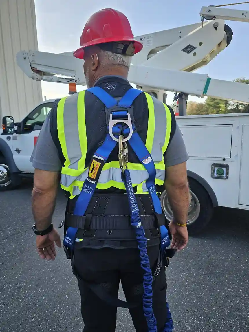
Self-Retracting Lifeline vs Shock-Absorbing Lanyard
Between a self-retracting lifeline (SRL) and a 6 ft shock-absorbing lanyard, connector selection is decided by one number before any other: the clearance between the anchor and the nearest obstacle below. Both are compliant connectors; only one may physically stop the worker before the ground, the platform edge, or the steel below the work point. Everything else is secondary arithmetic.
The decision is made with a tape measure and a set of labeled values, not with catalog preferences. This page lays out the arithmetic both device families force on the specifier: the clearance stack a 6 ft lanyard leaves behind, the arrest distance an SRL spends instead, the ANSI/ASSP Z359.14 label vocabulary that governs new procurement, swing fall geometry, anchorage ratings, and the inspection and rescue obligations that follow the purchase. The anchorage, the connector, and the fall arrest harness are one system; the connector chapter of that system is what follows.
Standards referenced throughout: OSHA 1926.502 and 1910.140 for the enforceable minimums, ANSI/ASSP Z359.14 for self-retracting devices, and the companion ANSI/ASSP Z359 documents for harnesses, energy absorbers, and anchorage connectors that complete the system.
This guide is aimed at safety engineers, erection crews, scaffolding erectors, and procurement teams. It covers 6 chapters: the selection problem, arrest physics and the clearance stack, device taxonomy and duty boundaries, the datasheet decode, a selection sequence with cost comparison and an RFQ checklist, and field practice from inspection to retirement. Standards referenced: OSHA 1926.502, 1910.140, and ANSI/ASSP Z359.14. Seven FAQs close the page.
Chapter 1 / 06
The Problem Is Clearance
Fall arrest does not mean preventing a fall from starting; it means stopping it, within limits the body survives, before the worker reaches a lower level. A personal fall arrest system has a geometric budget: the total distance from the start of the fall to full stop must fit inside the distance available. Equipment selection is the act of fitting those two numbers together, and it is the first thing a compliance review reconstructs after an incident.
The system has four parts: an anchorage rated 5,000 lb per attached worker under OSHA rules, or designed by a qualified person with a safety factor of at least two; the connector; a full body fall arrest harness; and a rescue plan. The connector is the only part with a genuine family choice, and that family choice is what this page decides. Both families hold the same legal status; neither is a downgrade. What separates them is physics: how much distance each one needs to bring a falling body to rest while holding average arresting force under 1,800 lb, which is about 8 kN, at the harness D-ring.
A lanyard is a fixed-length strap with a tear-out energy absorber. It needs its full length of free fall plus the absorber extension to dissipate energy: the worker falls the whole 6 ft before anything resists, then the absorber rips open across an additional stretch of distance. An SRL is a drum-wound line under slight spring tension that locks on acceleration, like a vehicle seatbelt: braking begins within inches of fall onset. One device spends feet, the other spends inches, and that difference decides which device is admissible at any given work point.
The selection problem therefore has a fixed order. First, compute required clearance for the candidate connector from its label values and the worker dimensions. Second, compare against the available drop from the anchorage to the nearest obstacle below, which is rarely the ground: it is the mezzanine deck, the rebar mat, the conveyor, or the lower chord one story down. Third, if both families fit the geometry, choose on mobility, service burden, and cost. Reversing that order, choosing a connector first and hoping the geometry works out, is the most common fall protection specification error in industrial procurement.
Vocabulary note. Self-retracting lifeline (SRL) is the umbrella trade term; the standards now say self-retracting device (SRD) to cover the whole family, from a short self-retracting lanyard worn on the harness to a 65 ft cable device on a davit. This page uses SRL for the family and names the subtypes where the distinction changes the decision. Lanyard here means a shock-absorbing lanyard, a fixed-length web or cable connector with an integral energy absorber, distinct from a positioning lanyard, which holds a worker at a work face and arrests nothing.
One more framing number before the arithmetic: the worker. Devices are labeled for a maximum user capacity, typically 310 lb (140 kg) including tools under the ANSI/ASSP Z359 family, and OSHA caps the average arresting force on the body at 1,800 lb. Every clearance and force number in the following chapters lives inside those two constraints, and equipment ordered without checking them against the actual crew weight plus tool load is equipment ordered twice.
Chapter 2 / 06
Arrest Physics and the Clearance Stack
A falling worker is an energy problem. The body accumulates kinetic energy over the free fall distance, and the connector must dissipate that energy while keeping the average force on the body below 1,800 lb (8 kN), the ceiling OSHA sets in both construction (1926.502) and general industry (1910.140). Double the free fall distance and the absorber must dissipate roughly double the energy, which is why free fall is capped by rule and why every extra foot of drop demands more deceleration travel, never less.
The lanyard route. OSHA allows up to 6 ft of free fall for a personal fall arrest system, and the 6 ft shock-absorbing lanyard is built exactly to that allowance. Anchored at D-ring height, the worker free falls the full 6 ft before the web comes taut and the rip-stitch energy absorber begins to deploy. The absorber tears in a controlled way, spending deceleration distance to keep the arrest force survivable; the regulation permits up to 3.5 ft of deceleration distance, but many labels state 4.5 to 5.0 ft of deployment, and the label value, not the regulation, is the number that goes into the clearance calculation.
Component
Distance
Basis
Free fall (lanyard length)
6.0 ft
OSHA maximum free fall allowance
Deceleration distance
3.5 ft
OSHA ceiling; labels often 4.5 to 5.0 ft
D-ring shift and harness stretch
1.5 ft
Standard allowance under load
Worker feet to D-ring
5.0 ft
Body dimension under load
Safety margin
2.0 ft
Good practice for error and stretch
Total required clearance
18.5 ft
Measured below the anchorage
Read the stack from the anchor down: 6.0 ft of free fall, 3.5 ft of deceleration at the regulatory ceiling, 1.5 ft for D-ring shift and harness stretch as the back D-ring rises under load, 5.0 ft from the D-ring to the soles of the boots, and a 2 ft margin for anchorage stretch, sole compression, and survey error. The 18.5 ft class total is why a 6 ft lanyard is the wrong tool below roughly 18.5 ft of available drop. Anchor position matters as much as length: raise the anchor above the D-ring and the free fall grows past 6 ft, which requires an absorber rated for the larger free fall and lengthens the stack further; lower it and the same geometry problem appears from the other side.
The SRL route. A self-retracting lifeline pays out under slight tension and locks when the line accelerates, so braking begins almost at fall onset rather than after a 6 ft drop. Arrest travel is bounded by the device label. Under the 2014 edition of ANSI/ASSP Z359.14, Class A devices were permitted up to 54 in of arrest distance and Class B up to 42 in; the 2021 edition reorganized the family into Type 1 (overhead anchorage) and Type 2 (also foot-level tie-off), with a 42 in maximum arrest distance across both types. With the line near vertical overhead, required clearance collapses to a small payout, plus the labeled arrest distance, plus D-ring shift, body dimension, and margin: roughly a 6 ft class budget where the lanyard needed the 18.5 ft class. That factor of roughly three is what makes low-level steel, mezzanine edges, and the top decks of scaffolding workable at all.
Force behaves differently too, and the difference is a design constraint, not a bonus. A lanyard absorber trades distance for a flattish force curve; an SRL uses an internal drum brake or energy absorber to do the same work in less travel, and both must hold average arresting force under 1,800 lb at maximum user capacity. A device that stops the worker harder than that ceiling is non-compliant even if it stops shorter: the standards buy survivable deceleration, not minimum distance at any cost. Devices with internal absorbers commonly publish average arresting forces of 900 to 1,350 lbf, comfortably inside the ceiling, and those numbers belong in the RFQ comparison, not just the arrest distance.
Attribute
6 ft Shock-Absorbing Lanyard
Overhead SRL
Braking onset
After full 6 ft lanyard payout
Within inches of fall onset
Arrest travel
3.5 ft ceiling; labels often 4.5 to 5.0 ft
Class A up to 54 in, Class B up to 42 in (2014); 42 in max under Z359.14-2021
Typical required clearance
About 18.5 ft below the anchor
Roughly 6 ft class with overhead anchor
Line behavior during work
Fixed length; slack managed by the user
Self-retracting; no slack to manage
Average arresting force
Under 1,800 lb (8 kN)
Under 1,800 lb (8 kN); often 900 to 1,350 lbf
Allowed anchor position
At or above D-ring height per label
Overhead; foot level only if Type 2 rated
Relative cost and upkeep
Low purchase; glance inspection
Higher purchase; scheduled service
The comparison table is the argument of the whole page in seven rows: identical legal status, identical force ceiling, a factor of roughly three in required clearance. Where the drop exists, both devices protect; where it does not, only the retractable one does, and no purchase order changes that.
Chapter 3 / 06
Device Taxonomy and Duty Boundaries
The SRL family is wider than the catalog picture of a steel box on a bracket. ANSI/ASSP Z359.14 and its companion documents sort the family by working length, by permitted anchorage position, and by function, and the boundaries between categories are duty boundaries: crossing one without the matching rating voids the engineering, whatever the clearance arithmetic says.
By size. A personal SRL, often called a self-retracting lanyard, carries roughly 8 to 20 ft of web or Dyneema lifeline in a compact housing worn on the harness back plate or hung at the anchor; it covers one worker at short range and is the volume product for general industry maintenance. A full SRL carries an integral lifeline, typically wire cable, in a drum inside a robust housing. The SRL-LL, the self-retracting lifeline with integral lifeline over 20 ft, extends working length to 65 ft and beyond for shafts, vessels, tank interiors, and long vertical runs. Over 20 ft the classification, the service regime, and the swing and rescue questions all change character, so the RFQ should name the category explicitly rather than trusting the cable reel photograph on the datasheet.
By anchorage. Type 1 devices (2021 vocabulary) and the pre-2021 overhead devices are certified for anchorages above the D-ring only; a Type 1 device anchored below the D-ring is a misapplication regardless of how much drop exists, because it was never tested for the longer fall and the line angles that result. Type 2 devices are tested for foot-level tie-off and the leading-edge condition, where the line runs over an edge and may contact it under load; they carry edge-impingement provisions, and foot-level tie-off needs that leading-edge rating plus the Class B (42 in class) arrest distance, because the fall distance before braking includes the whole height of the worker above the anchor plus body length. Note the vocabulary change explicitly: equipment built to ANSI/ASSP Z359.14-2014 carries Class A and Class B labels, equipment built to the 2021 edition carries Type 1 and Type 2, and installed fleets contain both. Procurement should specify by the 2021 types and train inspectors to read both vocabularies on old labels.
By function. Industrial SRLs arrest and hold; they do not lower. Descent-control devices, the rope descent systems used for window cleaning and facade access, and powered descenders are separate equipment families under separate standards, and they must not be substituted for fall arrest devices or vice versa. In the other direction, some industrial SRLs offer integral rescue raise and lower functions that shorten the interval between arrest and rescue; Chapter 5 treats that as a selection factor with measurable value, not a cosmetic option, because the rescue interval is what decides outcomes in a suspension event.
Swing fall is the geometry tax on all of it. When the anchor is not above the worker, arrest leaves the worker on a pendulum: they swing along the arc into the structure, and the horizontal offset adds both impact hazard and distance, because the diagonal line pays out longer than the vertical drop alone. A 30 ft lateral offset on a long line can add feet of effective fall and slam the worker into the steel at the end of the arc. The controls are geometric: keep the working angle to the anchor small, with 30 degrees off vertical a common planning limit; move the anchor with the work on a trolley or horizontal lifeline; and survey the swing landing zone, not just the drop zone, when measuring obstacles below.
The lanyard family is equally structured. Single-leg shock-absorbing lanyards, typically 4, 5, or 6 ft, are the base connector where clearance exists and the anchor stays near D-ring height. Double-leg versions with two snaphooks and a Y junction enable 100 percent tie-off: the worker always has one leg clipped while moving the other, which matters on horizontal pipelines, tower climbing, and any traverse where a single-leg device would leave gaps; the second leg must never be clipped back to the harness except at an approved attachment point. Positioning lanyards on side D-rings hold the worker hands-free at the work face, and they are positioning or restraint devices, not arrest devices. A fall arrest harness with positioning D-rings lets one harness serve both roles, but only the dorsal or sternal connection with an arrest-rated connector counts toward fall arrest, and the label on the harness says so.
Work condition
Device family
Governing requirement
Overhead anchor, drop under 18.5 ft
Personal SRL or full SRL, Type 1
Labeled arrest distance fits the measured drop
Foot-level tie-off, leading-edge work
Type 2 with leading-edge rating, Class B arrest distance
LE rating plus 42 in class arrest distance; edge contact assessed
Wide horizontal front
Horizontal lifeline with SRLs, or double-leg lanyards
Engineered lifeline; swing geometry controlled
Tower climbing, 100 percent tie-off
Double-leg shock-absorbing lanyard or twin personal SRL
Both legs managed; clearance checked at every rest platform
Independent fall arrest SRL per worker plus platform suspension
Anchorage above the worker; rescue plan on site
Window cleaning, facade descent
Rope descent or powered descent system
Separate standard; not a substitute for arrest devices
Chapter 4 / 06
Key Specification Parameters
A datasheet for either family answers the clearance question in eight lines, and each line maps to a decision. The decode table below lists the parameters in the order a specifier should read them; the paragraphs after it explain what each one buys, and what it costs when it is read wrong.
Parameter
Typical catalog spread
What it decides
Working length
Lanyard 4 to 6 ft; personal SRL 8 to 20 ft; SRL-LL 20 to 65 ft plus
Coverage per anchor point; swing and rescue exposure grow with length
Labeled arrest distance
Class A up to 54 in; Class B up to 42 in; 2021 types 42 in max
The center of the clearance calculation; label value governs over class name
Average arresting force
900 to 1,350 lbf internal limits, all under 1,800 lbf ceiling
Body load at arrest; injury severity and comfort under suspension
Maximum user capacity
Typically 310 lb (140 kg) including tools
Headcount and tool-belt math; heavier crews need the bigger class device
Lifeline material
Galvanized or stainless cable; nylon or polyester web; Dyneema (UHMWPE)
Edge and spark tolerance, weight on the harness, drum wear rate
Quality of the pre-use check; grit and paint seal become visible
Certification marks
ANSI Z359.14; CSA Z259.2.2; EN 360
Jurisdiction admissibility and procurement compliance
Working length is range per anchor, not mobility per worker. A 6 ft lanyard covers a 6 ft radius around its snap point plus reach; a 50 ft SRL-LL covers a full vertical drop with one anchor installation. Length also sets the retrieval problem: the longer the line, the more the rescue plan needs mechanical assistance, because a lowered-by-hand rescue through 50 ft of shaft is not a plan.
Labeled arrest distance is the number the calculation runs on, full stop. Class names are shorthands for label values: when a 2014-label device says Class A with 54 in, the 54 in enters the arithmetic, not the class letter. Under the 2021 edition both types are capped at 42 in, which quietly tightens the clearance budget of any fleet refreshed to current production, a fact worth knowing when an old clearance drawing is reused for a new purchase.
Force and capacity work as a pair. Average arresting force separates a hard stop from a survivable one: internal absorber designs commonly publish 900 to 1,350 lbf, all inside the 1,800 lb ceiling, and lower numbers mean less spinal load at arrest and during any suspension interval. User capacity is typically 310 lb (140 kg) including tools, and this is where procurement meets reality: a 240 lb ironworker with a 40 lb tool belt and winter layers is inside the rating; the same worker with a power tool and material on the belt may not be. Heavier-capacity devices exist, and the RFQ should state the actual maximum crew weight plus tools rather than assuming the default.
Lifeline material trades edge tolerance against weight. Wire cable tolerates abrasion, sparks, and hot-work spatter and dominates long SRL-LL drums; web is light and economical and dominates personal SRLs but loses quickly to an unrated edge; Dyneema (UHMWPE) line cuts weight further for tower, wind, and utility climbing where every gram on the harness counts across a shift, at a price premium and with the contamination sensitivities covered in Chapter 6. Match the line to the worst edge and the worst chemistry on the site, not the average condition.
Housing material follows the environment. Polymer housings shrug off washdown chemicals and do not conduct, which matters near live electrical work; aluminum saves weight aloft; painted steel is the indoor economy pick; stainless housings belong in marine and food-washdown service. The inspection window is a small feature with a large safety role: a clear polycarbonate panel over the drum lets a pre-use check catch grit, paint seal, and bird-nested line before the device is trusted with a life. A window occluded by overspray is itself a fail condition, not a cosmetic defect.
Certification marks are jurisdiction. ANSI/ASSP Z359.14 governs US practice; CSA Z259.2.2 is the Canadian standard for self-retracting devices; EN 360 covers retractable type fall arresters in Europe. A device carrying only one mark is not automatically admissible under another regime, and cross-border projects or multinational owner standards should list the required marks in the purchase order rather than discover the gap at commissioning, when the hardware is already on the dock.
Chapter 5 / 06
Selection Decision Factors
Selection is a sequence, not a preference. Run the steps in order and the device family falls out of the geometry; skip a step and the sequence produces the wrong device with complete confidence. The steps below assume the anchorage, harness, and rescue questions are decided with the connector, not after it.
Measure available clearance from each anchorage to the nearest obstacle below, including swing landing zones, not the ground alone. Mezzanine decks, rebar, machinery, and lower chords claim lives; the survey is a drawing, not a memory.
Below about 18.5 ft of drop: lanyards are excluded; select an overhead-anchored SRL. If no overhead point exists, a Type 2 device with its labeled clearance is the remaining compliant option, and creating an overhead anchor is usually the better engineering answer.
Above 18.5 ft with anchor at D-ring height: a 6 ft lanyard is admissible. Recheck the stack with the absorber labeled deployment distance (often 4.5 to 5.0 ft) and recompute for any anchor position that pushes free fall past 6 ft.
Leading edge and foot-level tie-off: specify Type 2 devices with leading-edge ratings and the Class B arrest distance, or restructure the anchor overhead. An unrated line over an edge can sever or abrade through at the moment it is needed.
Sloped roofs and ramps: treat the slope as added fall distance and swing geometry. Anchor up-slope of the work, keep the line out of contact with unrated edges, and remember that roof-edge work with foot-level anchors is a leading-edge case with less margin, not a variant of the overhead case.
Confined entries and vertical vessels: use overhead anchor points on scaffolding, a davit arm, or a top flange bracket feeding a Type 1 SRL or SRL-LL down the vessel axis, sized so the labeled arrest distance clears the bottom constraint, with retrieval capability standing by at the entry point.
Platform work: on an aerial work platform or a suspended platform, anchor only to the manufacturer's rated points, never to guardrails or mid-rails; the OEM manual, not the crew preference, defines the anchor and the connector length. A short lanyard or personal SRL per the manual is the norm on boom lifts precisely because the platform itself can catapult the worker in a sudden movement.
Close the loop: rated anchorage (5,000 lb per attached worker per OSHA, or engineered by a qualified person with a factor of at least two), competent person inspection cadence, and a written rescue procedure with equipment on site before the first climb.
The rescue item is not boilerplate. A worker hanging in a harness loses the muscle pump that returns blood from the legs, and suspension trauma can render them unconscious in minutes, well inside typical municipal response times. The plan needs on-site capability to reach and lower a suspended worker: a rescue-rated SRL with raise and lower functions, a tripod and winch at the vessel entry, or a trained crew with retrieval gear. Stage the rescue kit and a first aid kit at the work front, not in the office, and post a warning sign at holes and leading edges so the hazard is marked for every trade that walks the deck, not just the crew that created it.
Anchorage is half the system and most of the engineering. OSHA accepts 5,000 lb per attached worker for a non-engineered anchor, or an anchor designed by a qualified person with a safety factor of at least two against the arrest load; horizontal lifelines are engineered items, not a cable pulled tight between two unverified points. The best anchor is the highest one: raising the anchor reduces free fall, keeps the SRL line near vertical, and shrinks the swing radius simultaneously, which is why engineered trolley beams above production lines and loading faces repay their cost in connector freedom. Where the only practical anchor is a rail on an aerial work platform or a bracket on scaffolding, the anchor geometry question is answered by the equipment OEM, and that answer goes in the plan.
Cost line
6 ft Lanyard
Personal SRL
SRL-LL (over 20 ft)
Relative purchase price
1.0 x
3 to 6 x
8 to 15 x
Inspection burden
User glance check plus annual competent person
Pre-use check plus annual service; seal often factory-only
Annual recertification with drum service records
Consumable cycles
Absorber and unit retired after any arrest
Line replacement cycles per maker schedule
Rewebbing and recertification cycles per maker schedule
Service life driver
Web age and absorber history
Brake and spring wear, line wear
Line wear at pulleys and edge guards
Cost per year in heavy use
Lowest
Moderate
Highest, amortized over coverage
The economics favor lanyards where geometry is generous and retractables where it is not, but the honest comparison is cost per covered work point. One SRL-LL on a davit covers a vessel entry that would otherwise need repeated anchor relocation; one shared overhead SRL on a trolley covers an entire bay that twenty lanyards would serve poorly and dangerously. Buy the geometry first, then the device, then the price.
Write the RFQ so quotes are comparable and the compliance paper arrives with the hardware. State explicitly:
The clearance drawing: anchor points, distances to obstacles below, swing zones, and the computed clearance budget for each work point.
Anchor locations and ratings: existing certified anchors, engineered systems required, and loads in lb or kN per attached worker.
Number of users and shifts, plus the maximum user weight including tools against the 310 lb (140 kg) class capacity.
Device type per ANSI/ASSP Z359.14-2021 (Type 1 or Type 2), the labeled arrest distance, and the certification marks required, whether ANSI, CSA Z259.2.2, EN 360, or a combination.
Rescue provision: integral rescue functions, retrieval equipment, and the trained personnel plan; suspension trauma onset is measured in minutes, so the provision is part of the connector purchase, not a separate department.
Training records and the competent person inspection program, with frequency and documentation format, so the delivered devices enter a live management system on day one.
Site chemistry: washdown, marine exposure, and hot work that set the lifeline and housing material choices from Chapter 4.
Chapter 6 / 06
Field Practice: Inspection, Service Life, and Documentation
Equipment that saved a life once cannot be trusted to save another. The inspection regime for both families has three layers: user pre-use checks, periodic competent person inspections, and manufacturer or authorized-service recertification, and the paper trail is as much a part of the product as the drum or the web. This chapter is what the RFQ's training and inspection lines are buying.
Before each use, the user checks what is visible without tools. On a lanyard: the absorber indicator is intact and unstretched; the web shows no cuts, burns, chemical glazing, or UV-stiffened folds; snaphooks and carabiners spring shut and lock; the label is legible with serial number and standard marks. On an SRL: the line pays out and retracts fully without hesitation or slack; the brake locks on a sharp tug, tested at a safe height and never by dropping a tool; the housing is uncracked; the inspection window shows clean, evenly wound line on the drum; and the swivel and hook function freely. Any fail condition removes the device from service on the spot, tagged out and segregated, not returned to the bin for the next crew to find.
Periodic inspection by a competent person follows the maker's interval, annually at minimum under common ANSI/ASSP Z359 practice, and more often in harsh or high-cycle service. The competent person works from records and function checks but does not open sealed housings: internal brake work, spring service, and reseal go back to the manufacturer or an authorized service center, and tampering with a sealed housing voids the certification. Harnesses are inspected on the same cadence for hardware, web, stitching, and tag integrity. Results are logged by serial number with date, inspector, findings, and disposition, and the log is what turns a pile of hardware into a managed equipment pool.
An arrest event retires the device. A lanyard whose absorber deployed, an SRL that locked under a body, and a harness that caught a fall all carry internal damage that no field inspection can clear: torn absorber packs, brake wear, stressed stitching, stretched web. They come out of service immediately and go back to the manufacturer for destruction, rebuild, or written return-to-service certification. The same discipline applies to any device that has been shock-loaded, even by a dropped tool: steel and web do not forgive on the second event.
Service life policies are manufacturer property, not industry constants. Common web-product policies run about 10 years from date of manufacture to retirement regardless of appearance, while hardware can remain in service indefinitely if inspection and recertification pass, and SRL-LL fleets typically run on rewebbing and recertification cycles set by the maker, with retagging after each service as part of the loop: a device without a current tag is out of service until it has one. Procurement should request the written policy from each maker, file it with the equipment records, and let the policy, not shop folklore, set retirement dates.
Harness fit is a live safety parameter, not a comfort item. The dorsal D-ring belongs between the shoulder blades: positioned too high, it pushes the head forward at arrest; too low, and D-ring shift grows the fall distance, which grows the Chapter 2 clearance stack with it. Shoulder and leg straps adjusted to a flat hand of slack, chest strap at mid-chest, and a fall arrest harness sized to the individual worker rather than shared across shifts are the baseline. A loose harness in a real drop can allow the worker to slip partially or fully out of it, which no connector choice can compensate.
Contamination is the quiet killer of retraction and web alike. Paint overspray seals an SRL drum so it cannot pay out; grit in the drum abrades the line with every cycle and fouls the brake; solvents and chemicals glaze webbing and dissolve stitching; concrete dust sets in brake mechanisms. Devices stored or used at painting fronts and masonry work need covers, extra inspection, and scheduled cleaning per maker instructions, and a device caked in paint is out of service until cleaned and cleared by a competent person. Hot-work spatter on web or Dyneema line is an immediate retirement of that line: the damage is invisible at the surface and total at the fiber.
Documentation closes the system: serial-numbered inventory, issue and return logs, inspection records, training records per worker, the rescue plan, and drill records. Safety certification programs, whether corporate management-system audits or client prequalification schemes, audit the equipment pool as a system: they sample serial numbers, match them to inspection records, verify that removed-from-service tags exist and that tagged-out devices are physically segregated. The wider PPE pool is audited the same way, and a site that runs fall protection well typically manages the rest in one register: safety helmet with chinstrap for work aloft, safety glasses and safety gloves for steel and rigging tasks, safety shoes at access and work areas, respirator readiness for confined-entry standby, first aid kit and rescue kit staged at the work front, and warning sign placement at every hole and leading edge. A program that can produce all of this in twenty minutes survives the audit; one that cannot produces findings, and findings have a way of arriving with the next incident report attached.
FAQ
How much clearance does a 6 ft shock-absorbing lanyard need?
Plan on about 18.5 feet below the anchorage: 6.0 ft free fall, 3.5 ft deceleration at the OSHA ceiling, 1.5 ft stretch and D-ring shift, 5.0 ft feet to D-ring, and 2 ft margin. Many absorbers deploy 4.5 to 5.0 ft per label, so recalculate with the labeled number; an under-clearance arrest over a lower level is a fatality, not a near miss.
How much clearance does an overhead SRL need?
Far less: a small payout plus the device arrest distance, up to 42 inches maximum under ANSI Z359.14-2021 (Class A up to 54 in and Class B up to 42 in on 2014-label stock), then D-ring shift, body dimension, and margin. With the line near vertical overhead, the total commonly lands in the 6 ft class, near one third of the lanyard figure. Always compute from the labeled arrest distance for your specific device.
What are ANSI Z359.14 Type 1 and Type 2 devices?
The 2021 revision of ANSI/ASSP Z359.14, effective August 2023, classifies devices by anchorage: Type 1 for overhead only, Type 2 also for foot-level and leading-edge use, both with a 42 inch maximum arrest distance. Equipment under the 2014 edition carried Class A (up to 54 inch) and Class B (up to 42 inch) labels, and that base remains in service; specify new procurement by type and read both vocabularies on installed labels.
Can I anchor an SRL at foot level?
Only with a Type 2 or leading-edge rated SRL, and only with the extra clearance its label requires: foot-level anchorage adds the whole fall distance before braking, plus edge contact that can abrade or sever the line. A Type 1 device below the D-ring is a misapplication. Whenever an overhead anchor can be provided, use it, because every foot of added anchor height buys clearance back.
What is the 1,800 lb arrest force limit?
OSHA caps average arresting force at 1,800 pounds (about 8 kN) in construction (1926.502) and general industry (1910.140); ANSI Z359 holds equipment to the same ceiling, and many devices publish lower internal limits of 900 to 1,350 lbf. The body tolerates only so much deceleration, so a device that stops harder is non-compliant even if it stops shorter.
What is a swing fall and how do I control it?
The pendulum created when the anchor is not above the worker: after arrest, the worker swings along the arc into the structure or past an edge. Control it by keeping the work angle small (30 degrees off vertical is a common planning limit), moving the anchor with the work on a trolley or horizontal lifeline, and surveying the swing landing zone. A swing also lengthens effective fall distance, so it belongs in the clearance calculation, not in a footnote.
Does every fall arrest plan need a rescue plan?
Yes, and it is a regulatory expectation, not a courtesy. A suspended worker can lose consciousness from suspension trauma in minutes, so the plan must get them down promptly: on-site rescue capability and equipment to reach and lower them, staged where the work happens. SRLs with integral rescue functions cut the arrest-to-rescue interval, which decides outcomes.