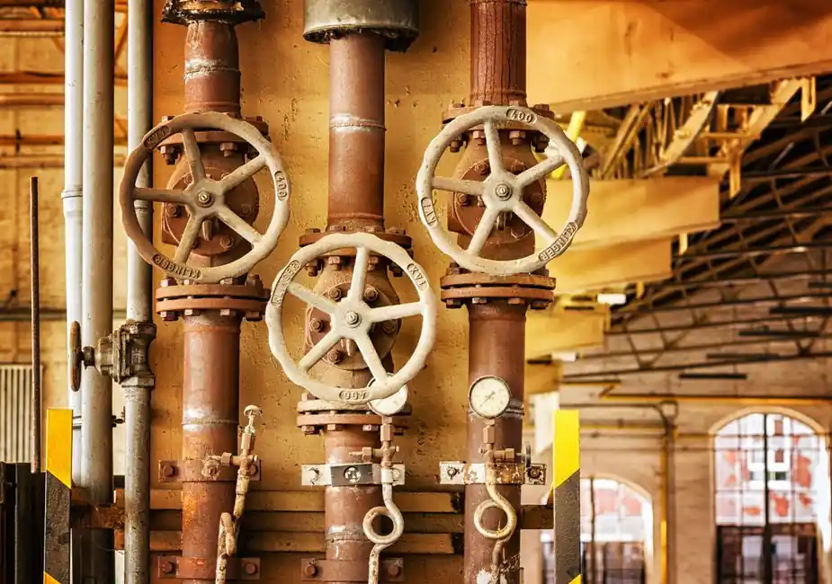
Selection must cover forward and reverse pressure, normal and peak flow, gas or liquid composition, allowable leakage, closing speed, orientation, corrosion, and installation restrictions, because a check valve must protect pumps, compressors, wells, pipelines, and storage systems from reverse flow [S2][S3][S5].
Define the service and failure consequence
A check valve opens with forward flow and closes against reverse flow, protecting mechanical equipment and maintaining pump prime; special installations may also require closure-member locking or removal so the valve can be deliberately held open [S2].
Oil and gas applications include subsea pipelines, wellhead assemblies, gas-lift systems, pump discharge lines, and storage tanks. The respective risks are seawater ingress, wellbore backflow, gas or oil entering injection lines, reverse rotation or damage to pumps, and contamination of supply lines [S1].
Do not select by pipe diameter alone. The governing envelope includes cracking pressure, forward-flow capacity, pressure loss, allowable back leakage, closure-member mass, service medium, and the consequences of failure [S4][S5]. A line-size valve can still operate poorly if its flow area or closure dynamics do not match the installed process conditions.
Compare the principal valve geometries
Spring-loaded, Y-pattern, and swing designs differ materially in pressure range, flow behavior, installation, and closure response; the most suitable geometry follows from the duty rather than a generic preference [S1].
Tilting-disc, diaphragm, and pilot-operated designs are additional options when closure behavior, venting, filling, draining, or controlled opening is required. Pilot operation can support fill-and-drain functions or deliberate override of non-return action [S3].
Size from flow velocity and pressure loss
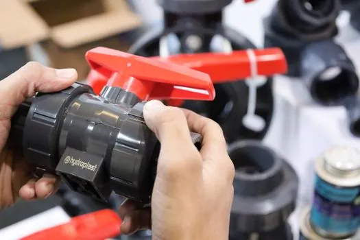
For liquid service resembling water, fully opening a check valve typically requires 10 to 12 ft/s, opening may begin near 4 to 8 ft/s, and the pressure drop needed to hold it open is generally two to five times cracking pressure [S5]. These values are sizing guidance, not universal ratings, and must be checked against the actual fluid properties and manufacturer sizing method.
An oversized valve may remain partly open, causing flutter, chatter, trim wear, and repeated shutdowns. An undersized valve creates excessive pressure loss, turbulence, and erosion [S5]. At minimum, calculate the pressure drop from normal and peak flow, confirm that minimum operating flow fully opens the valve, and verify that the reverse-pressure differential does not exceed the seat, closure member, spring, and body limits.
Gas service needs particular care because low density produces less opening force than liquid service, while decompression can materially alter the valve balance. Multiphase flow, entrained solids, viscosity, vapor pressure, density, abrasiveness, and chemical compatibility therefore belong in the sizing basis rather than being treated as footnotes [S5][S6].
Control reverse flow, leakage, and water hammer
Check valves close automatically when forward flow stops or reverses, but closure speed can damage piping if the stop is abrupt. Levers and weights, springs, air cushions, and oil dashpots can modify closing rate, while a backwash device may remove debris collected in the body [S5].
For reciprocating pumps and compressors, the closure sequence and cracking pressure must be coordinated with the drive system and discharge piping. Check valves also isolate standby machines from reverse rotation and maintain system pressure after a primary device stops [S2]. In pipelines, an uncontrolled closure can generate a pressure surge, so the valve supplier should evaluate the fluid and piping parameters against the proposed closure arrangement rather than treating slow closing as an optional accessory.
For small downhole tools, the leakage target may be more restrictive than the headline pressure rating. The Lee Company's product line includes a NACE-compliant version made from MP35N that resists pressures up to 15,000 psi. Such catalog limits establish feasibility, not automatic suitability; bore, flow path, seat material, temperature, chemistry, and cycle life still require confirmation.
Match materials to fluid and service environment
Body, trim, closure member, stem, spring, seat, and gasket materials must be evaluated separately because the wetted corrosion allowance cannot compensate for an incompatible spring, elastomer, or guide surface [S3][S4]. The selected combination must handle pressure, temperature, chloride exposure, sulfur-bearing service, erosion, and any production chemicals without creating unacceptable galvanic couples.
Compact oil-tool examples show the range of available configurations: ball-style or poppet-style elements, axial or side-exit paths, metal or elastomeric seats, and insert or cartridge bodies. The Lee Company's product line includes ball-style sealing elements and both axial and side-exit flow paths.
The cited extreme-environment range extends to 15,000 psi and 400°F, with five diameters from 0.125 to 0.500 inch [S4]. These figures describe a specialized supplier envelope. They do not establish that elastomer seats are appropriate for every hydrocarbon, steam, sour gas, or high-temperature duty, nor that a miniature valve can tolerate the flow velocity, particulate loading, and pressure cycling of a large production line.
Install for the actual piping arrangement
Spring-loaded check valves can be installed in any orientation, while swing valves require particular attention to horizontal flow, direction, and available installation space [S1]. The line must provide the specified straight lengths and support arrangements for the selected design, and the flow arrow must match the intended free-flow direction.
For horizontal swing installations, gravity-assisted closure, hinge orientation, and available headroom determine whether the design closes reliably when flow stops. An incorrectly installed swing disc can remain suspended, while an unsuitable spring or lever arrangement can fail to achieve the required cracking condition [S1][S5].
Subsea installation adds seawater exclusion, external pressure, corrosion, accessibility, and inspection constraints; wellhead service adds pressure cycling and restricted envelope; pump discharge adds reverse-flow damage and possibly water hammer; gas-lift service adds two-phase and decompression effects [S1][S6]. These service-specific constraints should be defined before comparing suppliers.
Apply standards and procurement controls
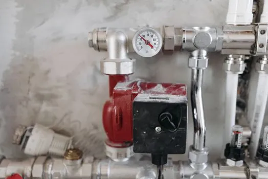
Spring-loaded check valves for oil and gas service can be evaluated against MSS SP-126, cited for typical characteristics, while project specifications may impose additional API, ASME, ISO, NACE, and client requirements for valve design, materials, testing, and documentation [S1]. Any cited standard must be applied to the exact rule it governs, with its stated edition confirmed during procurement.
A purchase specification should define the fluid composition, normal and peak flow, design and operating pressure, design temperature, allowable leakage, cracking pressure, minimum opening flow, allowable pressure drop, closure time, orientation, piping class, corrosion allowance, NACE requirement, coating, testing, marking, documentation, and spare-parts philosophy [S3][S4].
For typical service, use MSS SP-126 as a spring-loaded check-valve reference and require project-specific verification against the governing piping, material, and testing requirements [S1]. The Lee Company product information identifies an NACE-compliant MP35N option for pressures up to 15,000 psi, illustrating that sour-service material evidence and pressure capability can be specified together [S4].
Choose by the shortest defensible shortlist
Choose a swing check for low-pressure service where low forward loss, suspended solids, or pig passage dominates; choose a Y-pattern check for high-pressure service where reduced pressure drop is the priority; choose a spring-loaded lift check when fast closure, any-orientation installation, or controlled cracking is essential [S1].
Choose ball, piston, or poppet construction for compact or downhole packages where bore, leakage, and pressure dominate, and use pilot-operated or diaphragm arrangements only when fill, drain, venting, or controlled opening is part of the required function [S2][S3][S4].
Do not use the mainstream swing design when rapid closure, zero reverse leakage, or severe reverse pressure is central to the hazard. Do not use a compact high-pressure check valve when velocity, erosion, solids, or continuous cycling exceed its small-body capability. Final selection should close only after the manufacturer confirms calculated sizing, material compatibility, cracking pressure, leakage, closure response, installation limits, and applicable certification against the project data sheet.