
Coating thickness gauge selection in 2026 is driven first by substrate class (ferrous metal, non-ferrous metal, non-metal, or uncured powder) and only then by range, accuracy, and standards compliance, with magnetic and eddy-current dual probes covering the widest DFT workload at 0-500 μm [S1][S3].
For an industrial buyer, the practical decision is: pick a sensing principle that matches the substrate, pick a range that brackets the target DFT, and confirm the instrument declares conformity to ISO 2178/2360/2808 or ASTM D7091/B499 for metals, or ASTM D6132/ISO 2808 for non-metals, before evaluating cost [S3].
Substrate Class and Matching Sensing Principle
Coating thickness measurement splits into four substrate families, each with a primary non-destructive principle, as catalogued by current OEM offerings [S1][S3]. On ferrous substrates (steel, iron), magnetic induction measures non-magnetic coatings such as paint, enamel, galvanizing, and zinc plating; on non-ferrous substrates (aluminium, copper, brass), eddy-current principle measures insulating or non-conductive coatings; for both metal classes, dual-use gauges combine both principles in one probe and are the default choice when mixed-substrate work is routine [S1].
For non-metal substrates (wood, concrete, plastic, composite), ultrasonic pulse-echo is the established non-destructive method, with advanced ultrasonic models resolving up to 3 layers in graphics mode for paint and coating systems over concrete and plastic [S3]. For uncured powder coatings before cure, ultrasonic non-contact measurement predicts cured film thickness to avoid stripping and re-coating failures [S3]. A complete selection on metals, plastics, and concrete is covered in the coating thickness gauge reference page.
Range, Resolution, and Accuracy: Numeric Thresholds
Typical dual-use electronic DFT gauges span 0-500 μm with two resolution bands (0.1 μm from 0-99.9 μm and 1 μm from 100-500 μm) and state accuracy around ±(2%H+0.3 μm) after multi-point calibration, with repeatability near ±(0.8%H+0.1 μm) under fixtured conditions, where H is the standard reference value [S2]. These figures set the practical floor for QC-grade paint inspection on steel and aluminium automotive and process-plant structures [S2].
Plating lines, especially copper, zinc, tin, and chromium on ferrous substrates, routinely target films below 10 μm, which requires a probe designed around digital oscillation and high-speed ADC acquisition rather than generic analog front-ends, with a minimum measurement area of Ø7 mm to fit screw and bolt heads [S2]. For DFT work in the 50-2000 μm band, the same eddy-current family is offered in non-ferrous-only variants, complementing magnetic probes on a shared host [S1]. General instrument range and resolution definitions are summarised on the thickness gauge reference page.
Calibration, Geometry, and Field Constraints

Field-grade gauges typically support zero reference adjustment and 1-5 point calibration against coated thickness standards, which is the minimum number of calibration points to span both ends of the range and a midpoint [S1][S2]. Geometry constraints drive probe selection as much as the coating itself: convex minimum curvature 1.5 mm, concave minimum curvature 10 mm, minimum substrate thickness 0.1 mm, and minimum measurement area diameter 7 mm are common OEM limits for ultra-small plating probes [S2].
Operating environment also matters: 0-50 °C operation, -20 to 60 °C storage, and stable readings across temperature change are typical manufacturer ratings, with battery-powered handheld hosts (4× AAA, roughly 194 g including cells) standard for shop-floor DFT work [S2]. Where substrate is unknown on a mixed line, automatic substrate identification in a dual-use probe avoids manual mode switching and reduces operator error on the line [S1].
Standards Compliance and Method Selection
For metals, look for declared conformity to ISO 2178 (magnetic on non-magnetic coatings on magnetic substrates), ISO 2360 (eddy current on non-conductive coatings on non-magnetic metal substrates), ISO 2808 (general coating thickness methods), and ISO 19840 (DFT on rough steel substrates), alongside ASTM B244, B499, D1186, D1400, D7091, E376, and G12, with SSPC-PA2 procedure for field DFT verification and US Navy NAVSEA PPI 63101-000 and NAVSEA 009-32 for marine work [S3]. For mechanical pull-off gauges on steel, ASTM D7091/B499 and ISO 2808 are the baseline [S3].
For non-metal substrates, ASTM D6132 and ISO 2808 govern ultrasonic DFT on wood, concrete, and plastic, while destructive cross-sectioning on any substrate is anchored by ISO 2808/19399, ASTM D4138, JIS K 5600-1-7, and NF T30-123 [S3]. Uncured powder before cure falls under ASTM D7378, and wet film before cure under ISO 2808, ASTM D4414, AS/NZS 1580.107.3, JIS K 5600-1-7, and NF T30-125 [S3]. Hot-dip galvanizing on steel is covered by GB/T 13912-2002, "Metallic coatings, hot dip galvanized coatings on steel fabrications, technical requirements and test methods" (2022-06), which sets minimum local and mean coating mass and thickness acceptance for batch-dipped steel parts [S4]. Cross-reference coverage of coating types and DFT practice is on the industrial coating page.
Comparison: Main Options Against 4 Decision Criteria
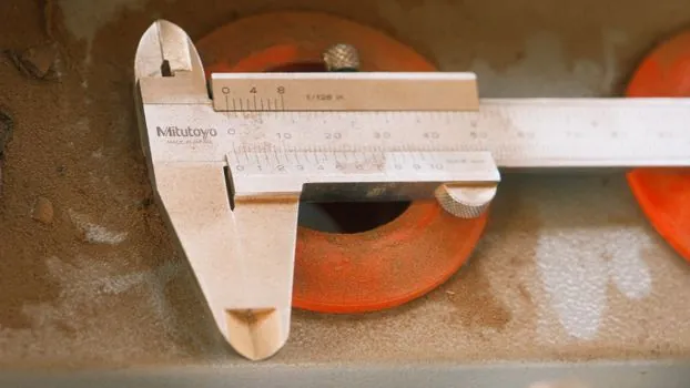
Side-by-side, the four practical options are dual-use electronic (magnetic + eddy) for all metals, magnetic-only pull-off (mechanical banana or pen) for non-magnetic coatings on steel, ultrasonic for non-metals, and destructive cross-section (Paint Inspection Gage) for any substrate when verification of a referee method is required [S1][S3]. On substrate coverage, dual-use and ultrasonic cover the widest field; pull-off and pen gauges are steel-only. On coating thickness range, dual-use electronic typically 0-500 μm, magnetic pull-off 0-2000 μm, and ultrasonic extending higher on thick elastomeric and polyurea systems. On standards fit, electronic dual-use and PosiTest DFT declare ISO 2178/2360/2808 plus ASTM B244/B499/D7091 and SSPC-PA2, while the destructive PosiTest PG aligns with ISO 2808/19399 and ASTM D4138 [S3]. On minimum measurement area, ultra-small plating probes reach Ø7 mm, which mechanical pen gauges often match or beat for pin-point placement on small parts [S2][S3].
Who Should Not Pick the Default Option
Do not pick a magnetic-only pull-off or pen gauge for non-ferrous aluminium extrusions, anodised aluminium cookware, or copper-alloy hardware: eddy-current is required because there is no magnetic response to read, and a magnetic gauge will simply not function on these substrates [S1][S3]. Likewise, do not pick an ultrasonic gauge for thin metallic DFT on steel; ultrasonic on metals is technically possible but is generally reserved for non-metal substrates, while magnetic or eddy methods give better repeatability below 500 μm on metals [S3]. For plating lines under 10 μm on small fasteners, a generic dual-use probe is usually too large; specify an ultra-small probe with Ø7 mm minimum measurement area and digital-oscillation front-end [S2].
Destructive vs Non-Destructive, and Lab vs Shop Floor

Non-destructive methods (magnetic, eddy-current, ultrasonic) are the default for production QC because they leave the part intact, while destructive methods (Paint Inspection Gage cross-section, metallographic microscopy, coulometric anode dissolution) are referee techniques used in lab disputes, failure analysis, and calibration of standards [S3][S5]. Metallographic microscopy via cross-section needs coating thickness above about 1 μm for the result to stay within measurement error, and the absolute error shrinks as the measured thickness grows, which is why it is the preferred referee method for thick industrial coatings and multi-layer systems such as Cu/Ni/Cr [S5]. Coulometric (anodic dissolution) is suited to single and multi-layer metallic coatings and alloy or diffusion layers, calibrated against coated standards of known mass per unit area, and is the standard method for plating bath QC in many shops [S5].
Shortlist Logic and Trackable Signals
Shortlist by substrate first: dual-use electronic for mixed ferrous/non-ferrous metals, magnetic-only mechanical for steel-only field checks, ultrasonic for wood/concrete/plastic, and destructive cross-section only for referee work [S1][S3]. Second filter: range and resolution. For ultra-thin plating under 10 μm, pick a digital-oscillation probe with Ø7 mm minimum area and ±(2%H+0.3 μm) accuracy after 1-5 point calibration [S2]. Third filter: declared conformity to the governing ISO and ASTM standards for the application, with SSPC-PA2 procedure for DFT on steel structures and ISO 19840 for rough steel substrates [S3]. Trackable signals to watch: revisions to ISO 19840 and SSPC-PA2 acceptance criteria for DFT on rough steel, broader adoption of multi-layer ultrasonic on concrete and FRP substrates, and continued displacement of mechanical pull-off gauges by electronic dual-use probes in automotive paint shops [S3]. For adjacent shop-floor metrology choices, see the roundness tester vs thickness gauge spec-first selection, and for ultrasonic on thicker sections, the ultrasonic thickness gauge reference page.