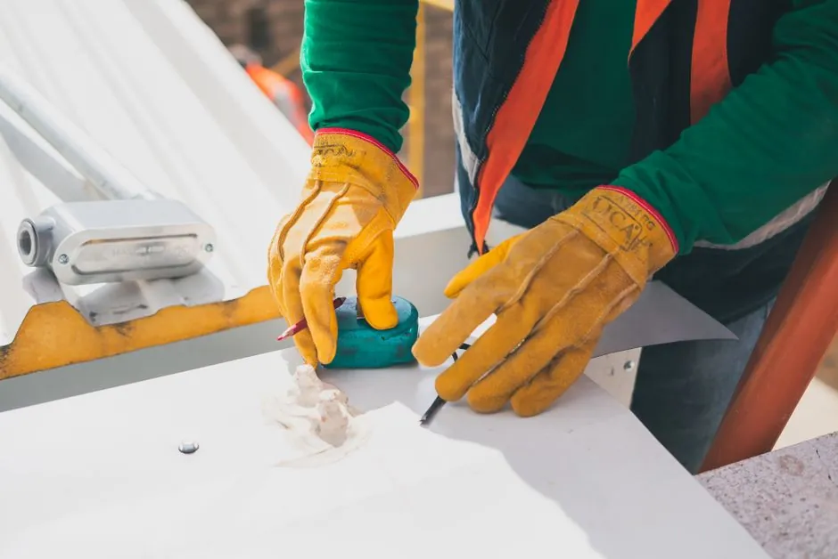
A correctly installed industrial filter rests on a level concrete pad, sits in a fully valved and gauged piping loop, and is loaded with cartridges only after the housing is confirmed at 0 psi on both upstream and downstream gauges [S1][S2].
Process plants, pools, and domestic RO skids all run variations of the same sequence: anchor, plumb, isolate, depressurize, drain, change element, reseat, leak-check, and bring the line up slowly with the air-bleed open. The numbers that matter are torque on the clamp, 0 psi before bowl removal, and a wet (never dry) O-ring on insertion [S1][S2][S4].
Pad, Foundation, and Equipment Placement
Install the filter on a flat, level slab of poured concrete, brick, or concrete block; never set a tank on wood, which warps and decays under the footings and lets the vessel drift out of level over time [S2]. Three placement rules hold across process and pool service: the surface must be level to prevent vibration and uneven seal loading, the filter should sit as close to the source as practical to keep the suction or feed line short, and the site must allow full drainage plus service access on all sides [S2].
Upsize the interconnecting pipe one nominal size when the filter has to sit remote from the process; longer piping runs cost head, and a one-step increase in diameter recovers most of the lost flow efficiency [S2]. For cartridge skids in clean service, wall-mount the enclosure on a rigid backing near the point of use, then run the plastic tubing, valves, and screws per the manufacturer's template rather than field-fitting [S3].
Isolation, Depressurization, and Drain-Down
Lockout the upstream pump or compressor and close the inlet isolation valve V1, then verify V2, V3, V4, and V5 are also closed before opening anything on the housing [S1]. Open the vent valve V7 and the drain valve V6 to empty the housing of process liquid; if a downstream drain V10 is present, crack it as well to drop the lower chamber [S1].
Do not loosen the housing bowl or clamp band until gauges G4 and G5 both read 0 psi, because pressurized air or steam in a cartridge vessel can separate the lid from the tank with enough force to cause severe injury or death [S1][S4]. On a clamp-band tank, stand clear of the filter while it is filling, since an unevenly seated clamp is the most common cause of a blowout during the first pressurization [S2].
Cartridge and Filter Element Change-Out
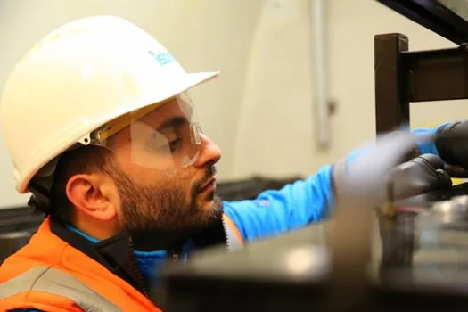
Keep the new filter in its protective bag until the moment of insertion; cut the bag open only at the O-ring end, wet the seals with water or the process fluid, and never touch the media with bare hands or fingers, since skin oils foul hydrophobic membranes and pleated surfaces [S1]. Push the O-ring end into the housing head with a twisting motion to seat the seal evenly, and on 2-226 or 2-223 tab configurations confirm that the locking tabs engage the tab holders in the head before removing the bag [S1].
Reinstall the housing bowl (or lid and clamp ring), then close the vent V7 and the drain V6 or V10 in that order before cracking the inlet [S1]. On clamp-band vessels, tighten the band to the manufacturer's torque specification with a calibrated wrench, then tap the clamp around the perimeter with a rubber mallet or hammer handle to seat it evenly; many modern bands include a spring assembly that signals correct tension [S2][S4]. A reference for the wider taxonomy of cartridge, bag, and self-cleaning formats sits in this encyclopedia entry on industrial filter types; the change-out mechanics described here apply across all of them.
Safe Start-Up: Air Bleed, Pressure Ramp, and Leak Check
Open the manual air relief valve on top of the filter before starting the pump, run the pump, and close the bleed only when a steady stream of water emerges with no air, because trapped air pockets slam the cartridges and skew the differential pressure reading [S2][S4]. Bring the system up to operating pressure in stages while watching the clamp band, the head seal, and all flange joints for weeps; a 5 to 15 minute slow ramp is standard for cartridge housings that were opened to atmosphere [S1][S4].
Record the clean differential pressure across the housing at first flow, because that baseline defines when the element is spent: most cartridge and bag elements are pulled at 1.0 to 1.5 bar (15 to 22 psi) differential, although heat-sanitized or steam-sterilized lines also need a temperature gauge and a mass flow meter in place to support integrity testing [S1]. For further reading on the cost side of that change-out interval, the engineering brief on industrial filter TCO walks through how pressure drop drives service life and lifecycle cost.
Common Failure Modes During Installation
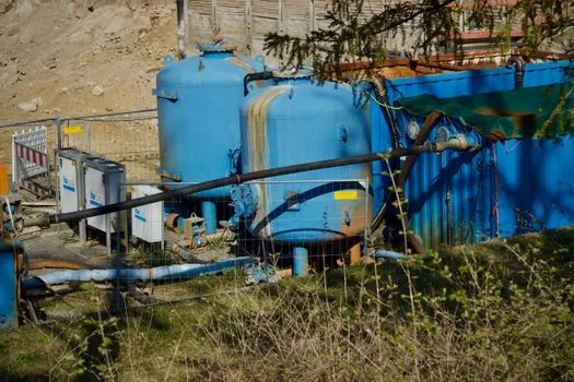
Four symptoms cover most first-start failures: weeping at the head seal, the filter going out of round over time, an unexpectedly high clean differential pressure, and a clamp-band blowout. The root cause for all four is almost always seating, not the element itself [S1][S2].
A weeping head seal traces to a dry, pinched, or contaminated O-ring; the corrective action is to remove the cartridge, inspect the groove, re-wet the seal with the process fluid (never a silicone grease that is incompatible with the media), and reseat with a twist [S1]. A tank that drifts out of round points to uneven clamp tension; re-torque to spec and re-tap the band with a mallet [S2]. A high clean delta-P on a new element usually means the wrong micron rating was pulled from stores or the flow direction arrow is reversed, and the corrective action is to swap to the specified rating and reorient the cartridge [S1]. A clamp-band blowout during pressurization means stop, do not approach the vessel, re-depressurize, and re-seat the band and O-ring before the next attempt; if the band or groove is damaged, replace the assembly rather than re-using it [S2][S4].
When to Call the Manufacturer Instead of Re-Trying
Escalate to the OEM or a qualified service company when the housing shows scoring on the O-ring groove, when the clamp band has yielded (permanent set) past its spring tension, when integrity testing fails after a sanitize-in-place cycle, or when the first-start differential pressure exceeds the housing's rated clean delta-P at the design flow [S1][S4].
Track two signals on the next service interval: the dry weight or clean delta-P recorded at this start-up, and the date the O-rings and gaskets were last replaced. If the clean delta-P at the next change-out rises more than 10 to 15% above this baseline, the housing is likely seeing a wrong-rating element, a bypass event, or a deformed gasket, and the root cause should be investigated before the next cartridge goes in [S1][S2].