
Type R thermocouple linearization requires four polynomial equations over -50°C to 1,767.6°C, while a transmitter converts the nonlinear millivolt signal into a standardized linear output [S1].
Type R and S thermocouples are among the standard thermocouple types that differ in material pairing, temperature range, sensitivity, long-term stability, resistance to specific atmospheres and typical application [S5].
Why Type R and S Output Is Not Temperature
Thermocouple output is thermoelectric EMF, not a linear millivolt-per-degree signal, except across narrow temperature intervals [S1]. The reference tables in IEC 60584-1 assume a 0°C reference junction, so a transmitter must apply both sensor linearization and cold-junction compensation before presenting a valid temperature [S1][S2].
The Type S letter identifies a defined temperature-voltage relationship rather than one fixed chemical composition; different manufacturers can vary the material construction while retaining the Type S calibration [S4]. A thermocouple remains appropriate for high-temperature measurement because it covers a wide range, responds quickly and is self-powered, although its output is only in the millivolt class [S2][S4].
Type R and S are platinum-rhodium thermocouples [S5]. Their small signal makes wiring, electrical interference, polarity and reference-junction temperature central parts of transmitter commissioning rather than secondary installation details [S2][S5].
How the R and S Linearization Is Implemented
Type R is the more demanding curve because covering -50°C to 1,767.6°C requires four polynomial equations, from third to seventh order [S1]. IEC 60584-1 also provides comprehensive EMF-versus-temperature tables and mathematical approximations for standard thermocouple types, giving equipment manufacturers a defined reference for implementation [S1].
Delta-sigma analog-to-digital converters are suitable for measuring the small sensor voltages produced by thermocouples [S2].
The IEC 60584-1 standard provides mathematical approximations of the nonlinear EMF-to-temperature relationships of standard thermocouple types [S1]. For a Type R thermocouple, IEC 60584-1 specifies four polynomial equations, ranging from third to seventh order, to approximate the relationship over the range from -50°C to 1767.6°C [S1].
Transmitter Output Options and Signal Chain
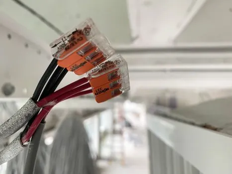
The TX13 head-mount transmitter accepts Type R and S thermocouple inputs and provides a two-wire 4–20 mA output [S6]. One listed head-mount design, the TX13, is a 2-wire 4–20 mA transmitter accepting Type K, J, N, E, T, R, S and millivolt inputs [S6].
For Type R and S applications, the transmitter must be configured for the correct thermocouple type, input range, polarity and output scaling [S5][S6]. Cold-junction compensation should also be verified because a transmitter or display requires an accurate reference-junction temperature to correct the thermoelectric signal [S2][S5].
A temperature transmitter is the right boundary device when downstream control, recording or alarm systems require a linear standard signal rather than raw thermocouple millivolts. Transmitters with Type R and S inputs are explicitly available in the market, confirming that these noble-metal sensor families are normal industrial transmitter inputs rather than specialist laboratory signals [S6][S7].
Transmitter Comparison Against Decision Criteria
For furnace, kiln, metal-processing and high-temperature service, Type R or S is appropriate only after the process maximum, atmosphere, stability requirement and installation method have been checked [S5]. Their noble-metal construction suits these high-temperature duties, but the transmitter specification should be matched to the same temperature range rather than accepted on sensor type alone [S5][S6].
Commissioning Checks That Prevent False Readings

Reversed polarity is a direct cause of incorrect measurement, so terminal marking must be checked before energizing a Type R or S transmitter [S5]. Selecting the correct thermocouple type requires consideration of the connection cable, polarity and transmitter [S5].
Reference-junction compensation introduces a measurable error if the terminal block is not thermally coupled to a known, stable temperature [S2].
Type R and S signals are vulnerable to electrical interference because their output is small and sensitivity can be in the microvolts-per-degree range [S4]. Shielded extension cable, correct routing, secure terminals and suitable input filtering protect the millivolt signal before linearization can deliver a stable 4–20 mA result [S2][S4].
Where This Signal Chain Fits
This architecture is for users who need a linearized process signal from a high-temperature Type R or S sensor, especially when an existing 4–20 mA control system cannot accept raw millivolts [S4][S6]. It is not the preferred choice where Type R or S stability, material cost or mechanical construction do not suit the process; Type K, J, T, N or E may offer a better fit for lower-temperature duties after range and atmosphere checks [S5].
Type R and S are generally less appropriate for low-temperature measurement because their output per degree is low at lower temperatures, and extension of the measurement span toward the bottom of the range can magnify signal and compensation errors [S3]. They remain appropriate when the process genuinely requires their noble-metal high-temperature characteristics and the transmitter has the corresponding coefficients and range [S3][S5].
Before procurement, track three items: the measured process span against the transmitter’s Type R or Type S range, the cold-junction compensation arrangement, and the configured output mapping [S1][S5][S6]. A traceable comparison against a calibrated reference at multiple temperatures will expose wrong sensor selection, polarity faults and incomplete compensation before the transmitter enters process control.