
The KOBOLD NMB is available with a rigid or flexible guide tube and an insertion length up to 15 m (50 ft) [S3].
The decision is driven by vessel height, available insertion space, process pressure, wetted-material compatibility, float construction, output protocol, and required installation mode rather than by probe type alone [S1][S3][S6].
Probe-length envelope and primary selection limits
The KOBOLD NMB offers rigid or flexible guide tubes, with insertion lengths up to 15 m (50 ft) [S3]. These ranges establish a practical split: rigid construction suits ordinary and compact tanks, whereas flexible construction extends the usable installation depth into tall storage vessels [S1][S3].
For short tanks, the rigid probe is mechanically simpler and requires no flexible guide assembly; for tall tanks, the flexible version can reach a level range that exceeds the stated 4,000 mm rigid limit of that model [S2].
The KOBOLD NMB provides a resolution of 0.1 mm (0.004 in) or 1 mm (0.04 in), depending on the version [S3]. Specify the required insertion length, active measurement span, dead zone, float travel, and allowable over-range before assigning a probe type.
Decision matrix: mechanical format against installation criteria
Rigid probes provide the shorter and simpler insertion envelope, while flexible probes provide the greater reach [S1][S3].
The KOBOLD NMB is available in a plastic-coated version for chemicals [S3]. The flexible format therefore has a material advantage in longer installation options, but its pressure rating is lower in that product family and must not be generalized to every model.
Against corrosion, KOBOLD lists PFA-coated stainless steel for flexible wetted parts and PFA, PVDF, or PP options for the plastic-coated rigid version, while the standard rigid tube uses 1.4571, or 316Ti, stainless steel [S3]. If the process contains aggressive chemicals, the coating and float material require separate compatibility checks rather than a generic stainless-steel assumption.
Pressure, temperature, and material constraints
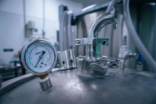
The KOBOLD NMB offers a plastic-coated version for chemicals [S3].
Float geometry affects whether the float remains stable and whether it can follow an interface. ABB K-TEK magnetostrictive level transmitters provide continuous level indication and control in critical and non-critical applications [S1]. For an oil-water interface, use a float selected for the density contrast and verify its full travel range, because a standard level float is not automatically suitable for interface detection.
Output, integration, and hazardous-area requirements
The KOBOLD NMB provides 4–20 mA and HART output, a graphic display, and a 99-point linearization table [S3]. HART is compatible with a 4–20 mA analog loop; FOUNDATION Fieldbus is a separate digital bus and should not be treated as interchangeable with HART [S1].
SP400 specifies 24–26 VDC power and RS485 communication, demonstrating that output architecture is model-specific rather than fixed by the magnetostrictive principle [S2]. The KOBOLD line includes a graphic display and supports volume and interface measurement [S3]. For an external mounting arrangement, an ABB unit can be mounted directly to a magnetic level indicator chamber, avoiding an additional vessel penetration and providing a continuous signal for PLC or DCS control [S1][S5].
For hazardous installations, the KOBOLD NMB variants include Ex ia IIB T6...T5 Ga, Ex db IIB T6...T5 Gb, and combined Ex db ia IIB T6...T5 Ga/Gb protection concepts [S3]. The APG MPXI-F flexible SS and PVDF series is explicitly designed for hazardous locations and tall tanks [S6]. Certification scope, zone, gas group, temperature class, and permitted wetted materials must be checked against the proposed model rather than inferred from the word flexible or from the housing alone.
Application fit and failure modes

A rigid probe is the stronger fit for a small underground tank, process vessel, bypass chamber, or compact installation where the required insertion length is within the stated 0.3–4.5 m range and a rigid element can be accommodated [S4]. It is less suitable when the vessel is tall, the available vertical insertion space is insufficient, or the required active measurement span exceeds the model limit [S3][S4].
A flexible probe is the stronger fit for tall vertical storage tanks, oil depots, crude-oil tanks, fuel installations, and reservoirs where the required reach is roughly 5–22.8 m [S1][S2][S4]. The flexible guide introduces installation-specific risks: it must be suspended and protected without sharp bends, its float and tube must remain aligned, and its lower pressure rating may constrain the application [S2][S3].
Both formats can be affected by a float that does not follow the liquid surface, deposits that prevent free movement, an unsuitable float density, or a process interface outside the calibrated travel. ABB states that its signal-to-noise behavior is not affected by vapors, emulsions, condensation, foam, or changing liquid-surface conditions [S1]. That statement concerns the sensing principle, not mechanical float travel or density compatibility, which remain separate design checks.
Installation selection and purchase specification
Specify the required insertion length, minimum and maximum liquid level, available installation height, process pressure, process and ambient temperature, fluid density, float material, coating, output, electrical classification, and whether the sensor is tank-mounted or externally mounted to a magnetic level gauge [S1][S3][S5]. For external MLI mounting, compare the magnetostrictive probe with other continuous options such as a magnetic level gauge, while recognizing that the MLI provides visual indication and the transmitter provides the control signal [S5].
A rigid probe is normally the lower-integration path when its 0.5–4.5 m range, 25 bar example pressure rating, and rigid mechanical support satisfy the installation [S3]. A flexible probe is normally the better path for a 5–22.8 m reach, with the 16 bar example rating and flexible-guide installation treated as the controlling constraints [S1][S3]. Obtain the selected model’s certified drawing and final datasheet before release, since length, pressure, temperature, float, coating, and approval combinations are model-specific [S1][S3][S6].