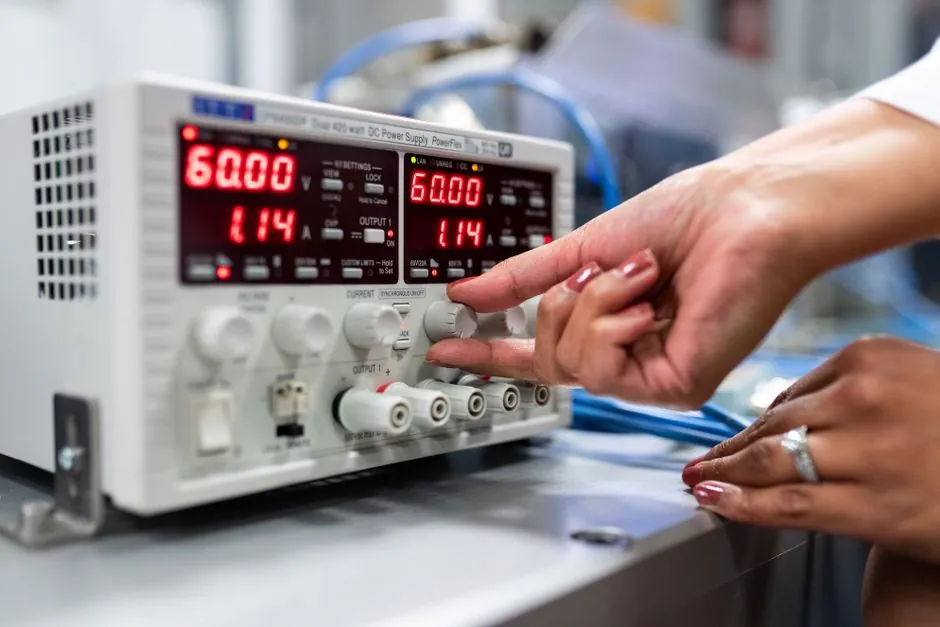
A resistance unit with 0.1 Ω resolution can simulate thermistors, strain gauges and pressure sensors [S4].
The setup suits bench and commissioning checks where engineers must reproduce wiring and receiver burden, but it does not replace a calibrated current source or transmitter reference.
What a decade resistance box simulates
A decade resistance box presents a selectable resistance in ohms, allowing an engineer to emulate a resistive load rather than connect the full physical loop. A listed dual-display resistance substitution unit provides 0.1 ohm resolution and is intended for sensor simulation involving thermistors, strain gauges and pressure devices [S4].
That matters because a 4–20 mA loop is a series circuit containing the DC supply, transmitter, field wiring and receiver load [S2]. The transmitter must develop 20 mA through the total resistance. Adjustable resistance is useful in assessing loop-burden issues involving the transmitter’s maximum load, supply voltage, wiring and receiver resistance [S2][S3].
The box is not itself a 4–20 mA source. For a transmitter-output test, use a loop calibrator to supply and measure the current while the decade box contributes the selected load. For a bare-input check, a loop tester can provide the diagnostic path.
Loop voltage and resistance limits
The controlling requirement is simple: the loop supply must exceed the sum of every voltage drop at 20 mA, including wiring, receiver input and the simulated load [S2]. Ohm’s law gives the load relationship, I = V/R; at 20 mA, a 250 ohm load consumes 5.0 V, while a 500 ohm load consumes 10.0 V.
The usable loop resistance depends on the transmitter’s specified maximum load at the applied supply voltage [S2].
Do not assume a nominal 24 V circuit has 24 V available at every terminal. Measure the supply under load, include the receiver’s voltage drop, and leave margin for the transmitter output rather than setting the decade box to its nominal maximum.
Choosing the right decade box
Selection should be based on maximum resistance, resolution, accuracy, power rating and connection method rather than decade count alone. The listed simulation unit offers 0.1 ohm resolution, but its usable current and power capability must be checked before inserting it into a 20 mA loop [S4].
A comparison of the main approaches separates functional checks from calibrated measurement. A decade box provides adjustable resistance but no independent current measurement; a loop calibrator provides current and measurement functions but may not reproduce every resistance step; and a deadweight tester applies calibrated mechanical pressure rather than electrical burden.
The same decision can be expressed across four criteria. A decade box is strongest for variable burden simulation and wire-fault diagnosis, weaker for traceable current output, and unsuitable by itself for pressure calibration. A loop calibrator is stronger for sourcing and measuring 4–20 mA, but less convenient when many cable-resistance values must be reproduced. A multifunction process calibrator is strongest for broad electrical calibration, while the decade box remains the simpler dedicated load simulator.
For automatic test equipment, fine resolution can be more useful than an extra decade because it permits narrower resistance increments and programmable load conditions. The listed model is marketed for automatic test use and resistive-sensor emulation with 0.1 Ω resolution [S4].
Resistance, burden and receiver interaction
Resistance and burden are related but not interchangeable. Resistance is the load in ohms; burden is the voltage drop that load produces across the loop. At 20 mA, burden equals loop resistance multiplied by 0.020 A, so 250 ohm produces 5.0 V and 500 ohm produces 10.0 V [S3].
A receiver with a current input has internal resistance, while a voltage-measuring receiver may use an external resistor across its input. Transmitters specify maximum load resistance at one or more supply voltages, and receivers specify input resistance or full-scale voltage drop [S3]. These two data sets must be combined before inserting the decade box.
Receiver burden must be considered because the receiver is part of the loop and can affect whether the transmitter reaches full-scale output [S3].
Where the objective is simply to assess a transmitter under realistic load, a decade box is practical. Where the objective is calibrated current measurement, use a loop calibrator or electronic load, and treat the resistance box as the load element rather than the measuring instrument.
Appropriate tests and unsuitable applications
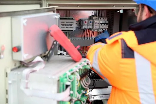
A decade box is suited to continuity checks, duplicate transmitter-output tests, receiver-burden experiments and repeated comparison of different cable lengths. It is also useful when a three-wire sensor installation must be checked through its signal and ground conductors, with the transmitter powered separately and the receiver providing the active current path [S1].
It is not the preferred tool for proving measurement accuracy, certifying a transmitter as a calibrated reference, or testing a loop without a safe power source. A simple adjustable simulator can cover 4 mA, 12 mA and 20 mA for basic connection checks, but voltage variation changes the resulting current unless a regulated source is used [S1].
Intrinsically safe circuits require additional control. A receiver with fault-current limiting slightly above a channel’s 20 mA demand can reduce ignition risk, while a cited receiver implementation uses a 100 ohm sense resistor to convert 4–20 mA into 0.4–2.0 V [S1]. Installing an unrestricted decade box into a hazardous-area circuit can defeat those safeguards unless the complete arrangement remains within the approved loop concept.
The box is also unsuitable for direct thermistor, RTD or strain-gauge calibration unless the instrument is specifically specified to emulate the required resistance range and measurement accuracy. The cited unit supports resistive-sensor simulation, but 0.1 ohm resolution alone does not establish total accuracy or temperature stability [S4].
Commissioning procedure and acceptance checks
Begin with a de-energized loop, isolate the intended load path and measure the actual wiring resistance with a low-resistance meter. Record the receiver burden at 20 mA, then select the decade-box resistance needed to reach the intended total burden without exceeding the transmitter’s voltage and resistance limits [S2][S3].
Apply the rated DC supply and verify the current at 4 mA, 12 mA and 20 mA. Use an independent loop calibrator or meter for this check. Repeat with the decade box at several settings, including the maximum planned field resistance, and watch for current drop, saturation or a receiver reading that no longer tracks the commanded value.
A transmitter that produces 4 mA but cannot reach 20 mA through the simulated burden is pointing to insufficient compliance voltage, excessive total resistance or a transmitter fault. A transmitter that maintains 20 mA but creates an incorrect voltage reading points more strongly toward receiver configuration, shunt selection or wiring. This separation is the core value of substituting known resistance for an unavailable physical loop.
For procurement and test records, capture the decade-box model, serial number, resistance setting, measured loop resistance, supply voltage, receiver model, current at 4, 12 and 20 mA, and the transmitter’s permitted load. Those records establish whether the instrument was used as a load simulator within its stated ratings rather than as an untraceable substitute for a calibrated transmitter simulator.
