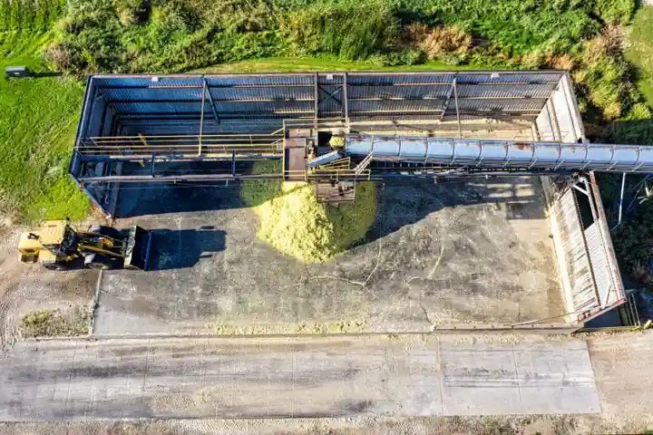
For a suspended hopper, tension-mounted S-type cells can isolate vertical force, while compression modules support a floor-mounted hopper from beneath.
The practical decision depends on support geometry, vessel movement, installation space, load capacity and the force paths that must not enter the measurement system.
Decision criteria for hopper weighing architecture
The first selection question is whether the hopper is suspended or supported from below, because S-type load cells are designed for tension applications and compression weigh modules are intended to support vessels from underneath [S2][S4]. Tension systems suspend tanks, hoppers and bins from an overhead structure, while compression systems place modules under each leg or support bracket [S1][S2].
Capacity is the second constraint.
Installation space, environmental exposure and vessel movement then narrow the choice.
Tension-mounted S-type cells: where they fit
S-type load cells with an S-shaped profile are suited to suspended hoppers and crane scales, measuring tension in hanging applications [S4]. In a tension arrangement, the cell is connected in the vertical load path with suitable eye-bolts, rod-ends or shackles; a rod-end or eye-bolt arrangement helps accommodate sway or rotation [S3].
Documented tension-module families include the 101NHM2, 110BHM3 and 363TSM1, with applications covering tanks, silos, hoppers and production-line weighing [S1].
A crane scale is a useful reference for the same tension-measurement principle, but crane lifting dynamics and hopper service dynamics should not be assumed to be equivalent.
Compression weigh modules: where they fit
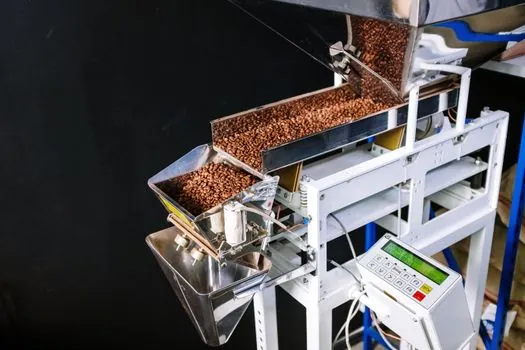
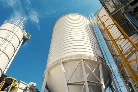
Compression modules support platforms, tanks and structures from underneath, with one module placed below each leg or support bracket [S1][S2]. For a floor-mounted hopper, compression load cells are preferred and their modules are described as compact and easy to mount in columns [S7].
Compression systems also require force isolation.
Typical module families listed for compression service include the 102 series, 563 series and 276EHM1 [S1].
Comparison by installation, capacity and integration
On installation geometry, tension-mounted S-type systems suspend the hopper from above, while compression modules support it from below [S1][S2].
When weighing an object that can sway or rotate, an S-type load cell is generally used with eye-bolts or rod-ends in tension [S3]. Neither option should be selected solely by cell shape: the module, cell and structure form one measurement chain.
For the broader force-measurement distinction between S-type and canister cells, see S-Type vs Canister Load Cells for Force Measurement.
Failure modes and commissioning checks
Lift, lateral restraint and shock are common failure paths for either arrangement. Weigh modules must provide anti-lift protection, lateral stops and overload protection so vessel tipping, wind loading or sensor overload does not occur [S1]. Tension installations also need controlled movement, because a hopper that can sway or rotate requires compatible eye-bolts or rod-ends in the cell connection [S3].
Thermal movement can create parasitic force in a rigidly tied hopper. Center-pivoted, self-aligning compression modules are specifically recommended for large outdoor vessels exposed to wide temperature swings [S1]. For a suspended design, flexible connections, adequate hanger length and controlled frame stiffness should be evaluated for the same reason.
Commissioning should include zeroing with the hopper empty, test loads at several points, comparison of individual corner readings and a check for corner-to-corner disagreement. If the hopper has flexible supports, unequal load sharing, a bypass pipe or a bonded grounding path, a scale indicator may report a plausible weight while the actual load distribution remains unsuitable for batching [S1][S4].
Environmental selection must include temperature, humidity, washdown exposure and corrosive agents, because these conditions affect load-cell performance and service life [S4]. Cable routing, junction-box ingress protection and corrosion resistance are part of the weighing system, not minor electrical accessories.
Recommended choice by use case
Choose a tension-mounted S-type assembly when the hopper must hang above the floor, overhead support steel is available, and the design includes proper isolation from lateral building loads. For hoppers with moving or rotating suspension points, specify the module and hardware for controlled multi-directional movement, as demonstrated by the 110BHM3 feature set [S1][S3].
Choose compression weigh modules when the hopper is floor-supported, the vessel has several defined support legs and under-hopper access is not the controlling requirement. This architecture is standard for floor-mounted hoppers and silos, with modules placed below the legs or brackets [S2][S7]. Use self-aligning hardware where thermal movement could otherwise shunt force into the structure [S1].
Neither arrangement is a universal default. Reject a tension design if the overhead frame can touch the hopper, the hangers impose side loads, or vessel impact will exceed the cell’s working range. Reject a compression design if the vessel cannot be isolated from the floor, support heights are incompatible with the module, or unequal leg loading cannot be corrected in the system design.
Before purchase, freeze the vessel weight, product capacity, fill rate, impact load, support coordinates, required accuracy and installation envelope. Compare complete module-and-cell packages rather than cell capacity alone, then verify the final installed load path with the piping, ladders, guards and cleaning system in their normal positions.