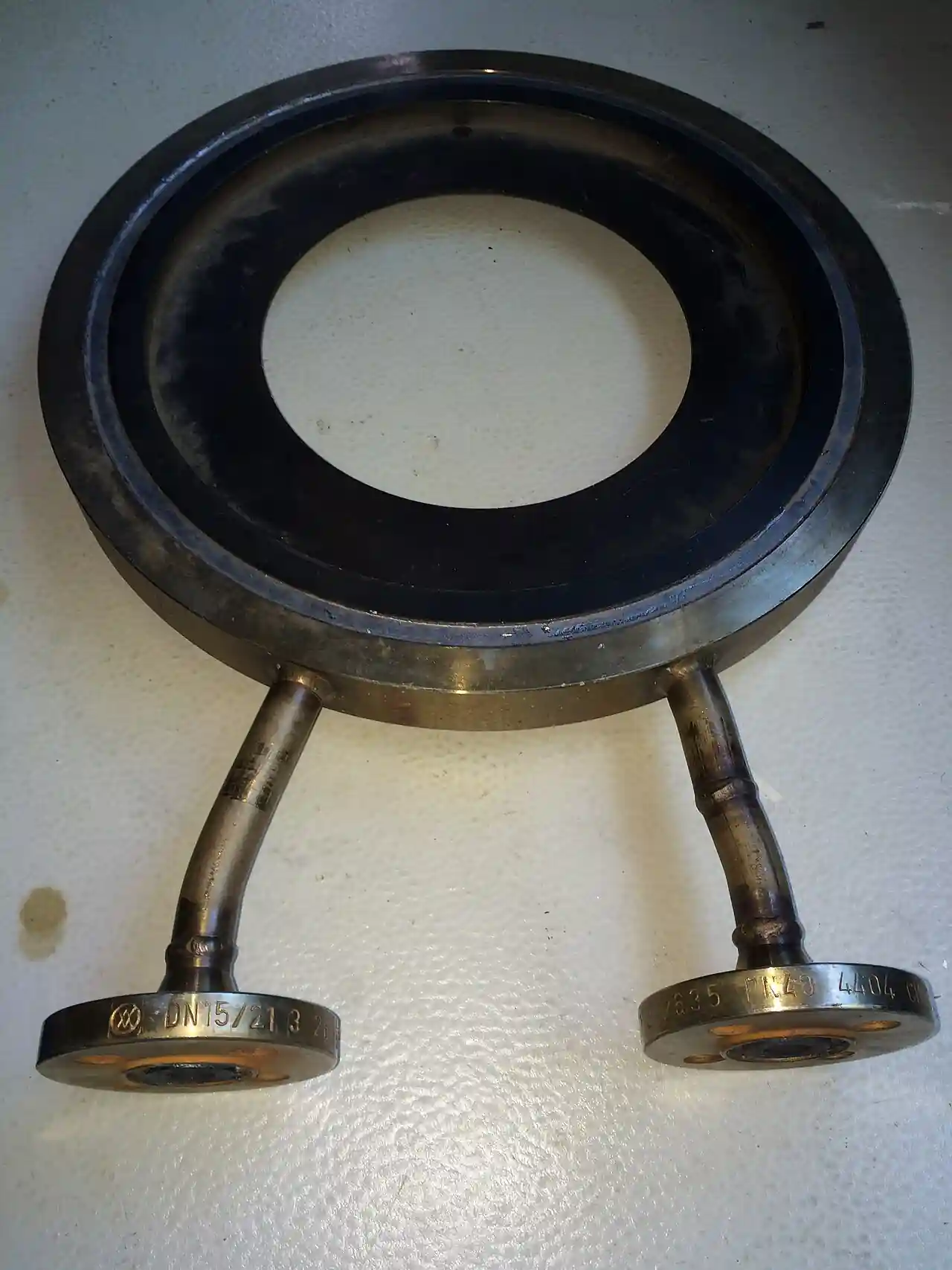
A flow nozzle is a differential pressure primary element consisting of a rounded convergent inlet profile that accelerates the stream into a short cylindrical throat, with no divergent recovery section behind it. The pressure difference between a tap upstream and a tap at or near the throat is measured by a differential pressure transmitter, and flow follows from the same square root law that governs every ISO 5167 element. The rounded profile is the whole point: it sheds particles, tolerates high velocity, and holds its discharge coefficient at Reynolds numbers where a sharp edged bore dulls or fouls within months.
Procurement engineers meet flow nozzles where steam is the fluid: saturated and superheated lines in power, process, and district energy plants, boiler feedwater at high velocity, and blowdown and flash lines. They also appear on wet gas, on erosive liquids, and as laboratory proved throat tapped elements in turbine acceptance testing. Sizes run from 50 to 630 mm by standard, with welded and flange held hardware beyond in vendor catalogs. The decision this page settles is when the rounded profile justifies itself: a flow nozzle costs several times an orifice plate flowmeter bore, wastes roughly a third of the measuring differential, and in exchange keeps measuring accurately at velocities and temperatures that destroy the cheaper element.
This page treats the flow nozzle as a purchasing object: the ISA 1932 and long radius profiles of ISO 5167-3, the beta ratio and Reynolds number envelopes by type, the tapping arrangements that define the hardware, the permanent loss that sets the energy price, and the erosion and impulse failure modes that decide whether the calibration survives. It is written for engineers who must specify steam metering that still reads true at the next outage.
Chapter 1 / 06
What a Flow Nozzle Is and What Is Being Decided
The flow nozzle earns its place in the ISO 5167 family through one geometric decision: the stream contracts along a smooth curved profile instead of turning at a square shoulder. The element is a shaped insert, machined or formed, whose inlet face follows a defined radius or ellipse into a cylindrical throat a fraction of the pipe diameter across; downstream, the jet discharges freely into the pipe. Because the profile is guided, the flow separates cleanly and the discharge coefficient sits near 0.96 to 0.99, far above the 0.60 of a sharp edged orifice plate flowmeter bore, and it stays there at velocities that would round over a square edge and shift its calibration.
Anatomy is brief by design. The convergent inlet of an ISA 1932 nozzle is a specific curved profile named in ISO 5167-3; a long radius nozzle uses a quarter ellipse with a generous radius of curvature. The throat is a straight cylinder, roughly half a throat diameter long in the ISA 1932 form and half to two thirds in long radius forms. There is no recovery cone, so the whole element measures about one pipe diameter in length, and the hardware is either a weld-in stub or a carrier ring clamped between pipeline flanges with the profile machined into a plate or welded ring.
The nozzle holds the middle of the differential pressure family on purpose. It recovers more pressure than an orifice plate flowmeter because the guided entry avoids the violent vena contracta, yet it recovers less than a classical venturi tube because there is no divergent section to slow the jet gently; permanent loss lands near 30 to 40 percent of the measuring differential, between the 50 to 60 percent of the sharp edged plate and the 5 to 15 percent of the venturi. Steam and high velocity service is where that middle is exactly right: enough recovery to be economical, enough compactness and erosion resistance to survive the duty.
What a flow nozzle RFQ actually decides is the pairing of profile and tapping. The ISA 1932 profile with corner taps is the steam workhorse, compact and accurate, but its coefficient depends on beta and Reynolds in ways the sizing sheet must expose. The long radius profile with D and D/2 pipe wall taps is gentler, covers a wider beta band, and tolerates bore uncertainty better. The throat tapped variant is a laboratory grade element for acceptance testing. Choosing one is a calibration decision that lasts as long as the plant, because taps cannot be moved after the weld.
Three commitments come with the purchase. First, a thermal duty commitment: high temperature steam demands alloy materials, welded construction, and impulse hardware rated for the line, all of them order line items rather than site improvisations. Second, a bore commitment: beta is computed on the measured pipe bore, and a schedule change moves it. Third, a maintenance commitment: throat erosion and tap condition set the drift budget, so access for gauging and flushing belongs in the layout. A quotation that ignores any of the three is incomplete regardless of price.
Chapter 2 / 06
How a Flow Nozzle Measures Flow
The measurement law is shared with every ISO 5167 element. Continuity accelerates the stream into the throat, Bernoulli converts the velocity gain into a static pressure fall, and mass flow equals the discharge coefficient, times the throat area, times the velocity of approach factor, meaning the reciprocal square root of one minus beta to the fourth, times the square root of twice the differential pressure and the density. What distinguishes the nozzle is where it sits in that equation: the coefficient term is large and stable at high Reynolds numbers, precisely the regime where the sharp edged alternative loses its calibration. The sizing sheet a supplier returns should expose each term, not just the answer.
Beta, the throat to pipe diameter ratio, spans 0.3 to 0.8 for ISA 1932 nozzles and 0.2 to 0.8 for long radius designs in ISO 5167-3. That band is the widest in the differential pressure family and it is a real advantage: a metering station can be re-ranged later with a new throat insert instead of a new spool, provided the measured bore was documented at installation. Signal sizing follows the usual discipline, with full scale differentials of roughly 10 to 50 kilopascals common on steam service; below that range the transmitter dominates the error budget, above it the permanent loss starts to matter against boiler pressure.
Discharge coefficients run near 0.964 for an ISA 1932 nozzle at mid beta, computed from the standard's formula in beta, and near 0.98 to 0.99 for long radius designs across their band. Published uncertainty sits below one percent for ISA 1932 at common beta ratios and about two percent for long radius. The striking property is behavior with Reynolds number: where a sharp edged coefficient wanders as its edge ages and as Reynolds climbs past a few million, the rounded profile holds, which is why fast steam lines and wet steam tolerate nozzles for decades between calibrations.
Tapping arrangements are part of the type definition. The ISA 1932 nozzle is read through corner taps, either individual bores at the plate face or an annular ring chamber, and the carrier hardware usually carries both tap connections machined in. The long radius nozzle uses pipe wall taps one diameter upstream and half a diameter downstream, which leaves the element itself almost hardware free. Throat tapped designs add a connection inside the throat for low loss measurement. On steam, every tap pair needs condensate pots mounted level with the line, so the differential pressure transmitter sees equal liquid legs on both sides and temperature swings do not read as flow. Line static pressure, read by a separate pressure sensor at the station, feeds the density compensation that the flow equation consumes on steam and gas.
Permanent pressure loss lands near 30 to 40 percent of the measuring differential, and the mechanism is visible: the jet leaves the throat at high velocity with nothing to decelerate it except turbulence in the pipe, and that dissipation is the loss. Against the 50 to 60 percent of a sharp edged plate the saving is real; against the 5 to 15 percent of a classical venturi tube it is modest. On boiler plant, where every kilopascal of main pressure is firing energy, specifiers run the same kilowatt arithmetic that justifies venturis on water, and accept the middle number in exchange for the smaller body and the tougher profile. The number is worth stating in the RFQ because two suppliers quoting the same duty can sit at opposite ends of the band.
Chapter 3 / 06
Types, Construction, and Duty Boundaries
The ISA 1932 nozzle is the reference type. Its convergent profile is a defined sequence of curved and straight segments named in ISO 5167-3, identical between manufacturers, which is what makes the standard's coefficients transferable to any qualified supplier. Pipes from 50 to 500 mm and beta from 0.3 to 0.8 are covered, with Reynolds floors that rise with beta in the standard tables up to an envelope reaching ten million. Corner tap hardware, ring or individual bores, completes the type. It is the default answer for saturated steam, wet steam, and most erosive duties.
The long radius nozzle sweeps the flow through a quarter ellipse of generous radius into a throat about half a diameter long, with separate low beta and high beta profiles defined in the standard. It spans pipes from 50 to 630 mm and beta from 0.2 to 0.8, and it reads through D and D/2 pipe wall taps rather than corner hardware. The gentler profile buys Reynolds stability and tolerance of pipe bore uncertainty, at about two percent coefficient uncertainty, and it is the usual choice on superheated steam and high velocity liquid where the flow is clean and fast. The two profile forms exist because a single ellipse cannot serve both a 0.2 and a 0.8 throat ratio without distorting the approach, so the standard publishes each with its own throat length and its own coefficient basis.
A third construction matters where measurement settles contract disputes. Throat tapped nozzles carry the low pressure connection inside the throat itself, are machined to tighter limits, and appear chiefly in turbine and pump acceptance testing under ASME PTC 6 and similar performance codes, where the element is proved in the laboratory and installed as a calibrated artifact. Procurement sees them as line items with calibration certificates and bore measurement records attached; nobody sizes a PTC nozzle from a catalog table.
The family also contains a hybrid that deserves one paragraph and no more. The venturi nozzle takes the rounded convergent profile of the nozzle family and adds a short divergent outlet behind the throat, recovering more pressure than a bare nozzle while staying shorter than a classical venturi body. ISO 5167-3 defines it with its own beta, diameter, and Reynolds envelope and its own coefficient treatment, and it is specified by that clause text, not as a modified version of either parent. On medium liquid and steam lines where the bare nozzle loses too much pressure and the venturi will not fit, it is the correct object to name in the RFQ.
Materials follow temperature and fluid. Bar stock 316 stainless steel is the catalog default for saturated steam, water, and clean hydrocarbon, with 316L chosen for weld-in bodies where corrosion at the seam matters. Superheated duty moves to chrome moly alloy steels matched to the pipe, sometimes with a stainless steel throat insert for weldability. Hardware splits between a carrier ring held between pipeline flange faces, quick to install and to remove, and a weld-in stub for high temperature classes where a gasketed joint is unwelcome. On erosive duty the throat entry gets a hardfaced or replaceable insert, and the RFQ states the hardness and the gauging schedule rather than hoping.
Type
Inlet profile
Pipe range
Beta
Taps
C basis
ISA 1932
Defined curved segments per ISO 5167-3
50 to 500 mm
0.3 to 0.8
Corner, ring or bore
about 0.964 at mid beta, standard formula
Long radius
Quarter ellipse, low and high beta forms
50 to 630 mm
0.2 to 0.8
D and D/2 pipe wall
about 0.98 to 0.99
Throat tapped, test grade
Machined to tighter limits
By project
By project
Upstream plus throat
Laboratory proved per PTC 6
Chapter 4 / 06
Key Specification Parameters
The datasheet lines below are the ones that decide equivalence between quotations. Each row maps to a clause that a weak quotation will leave out, and the paragraphs after the table explain how to close the gap.
Attribute
Typical range or options
What it decides
Profile standard
ISA 1932 or long radius per ISO 5167-3
Calibration basis and which taps are possible
Beta ratio d / D
0.3 to 0.8 ISA 1932, 0.2 to 0.8 long radius
Signal size, throat velocity, and re-range headroom
Pipe diameter
50 to 630 mm by type
Carrier ring or weld-in hardware and cost
Reynolds number
10,000 to 10,000,000 with beta floors
Validity of the standard discharge coefficient
Discharge coefficient C
about 0.964 to 0.99 by type
Accuracy claim without calibration
Permanent loss
30 to 40 percent of differential
Boiler and pump energy price of the measurement
Taps
Corner, or D and D/2, or throat
Impulse hardware, condensate pots, routing
Construction
Flange carrier ring or weld-in stub
Installation method, removal, temperature class
Materials
316 stainless steel, 316L, chrome moly alloys
Temperature and corrosion envelope
Upstream straight run
about 10 pipe diameters
Layout feasibility against competing elements
Pipe schedule effects deserve their own paragraph because they are the quietest way a project corrupts a nozzle calibration. Beta divides throat diameter by the pipe bore, and the bore is set by schedule: at 300 mm nominal, a shift from schedule 40 to schedule 80 moves the bore from roughly 303 to 289 millimeters, which is beta movement of nearly five percent and a proportional calibration shift. The fix is procedural: record the measured bore at the meter station, compute beta on it, and re-issue the datasheet whenever the pipe specification changes. The same discipline applies to an orifice plate flowmeter, and buyers who skip it on both read years of flow with a hidden bias.
The comparison table reads by rows against the two neighbors in the differential family. The nozzle owns the durability row: it is the element whose calibration survives high velocity and wet service, and every other number in the table is secondary to that one. The sharp edged plate wins cost and simplicity, the classical venturi wins pressure recovery, and against non differential options a vortex flowmeter on clean steam trades recovery for turndown and lower maintenance. The nozzle is bought when the first question is whether the meter will still be accurate at the next outage.
Parameter
Flow nozzle
Sharp edged plate element
Classical venturi
Inlet profile
Rounded, standard curves
Square sharp edge
21 degree convergent cone
Discharge coefficient C
about 0.96 to 0.99
about 0.60
0.984 to 0.995
Durability at high Reynolds
Strong, no edge to dull
Edge dulls and fouls
Strong
Permanent loss, percent of differential
30 to 40
50 to 60
5 to 15
Upstream straight run
about 10 D
10 to 40 D
0 to 5 D
Size envelope by standard
50 to 630 mm
50 to 1,000 mm
50 to 1,200 mm
Characteristic duty
Steam, wet and erosive flow
General clean service
Large liquid mains
Ordering traps collect quickly. A corner tap ring ordered without stating the pipe schedule arrives with the wrong stand-off; a weld-in stub ordered without a weld procedure is a site stoppage; a long radius nozzle ordered for a line whose actual bore was never measured carries a beta nobody can defend; and a carrier ring ordered against the wrong flange drilling is a receiving reject. Each trap is closed with one datasheet line, which makes it the cheapest quality action in the whole purchase.
Chapter 5 / 06
Selection Decision Factors and RFQ Language
Steam is the center of the flow nozzle map and the reason the type exists in most plants. Saturated steam carries water droplets, superheated steam runs fast and hot, and both dull a sharp edge by erosion and oxidation; a rounded profile simply outlasts the decade. The nozzle also sweeps solids through: there is no upstream face cavity for particles to pack against and no edge to chip, so wet steam with carryover, soot blower transients, and intermittent slugs all behave. Where the steam main is protected by a safety relief valve, the metering hardware is rated to the relief set pressure, and the impulse system is designed for the same temperature, a sentence that belongs in the RFQ rather than in site hindsight.
On liquids the nozzle earns its place at the velocity extremes. High velocity feedwater, erosive tailings water, and dense fine slurries all punish elements that present edges or cavities. Where the liquid is conductive and clean, an electromagnetic flowmeter is usually the better economics: no impulse lines, no density compensation, lower uncertainty at lower cost. The nozzle keeps the duty when the fluid is hot, nonconductive, or loaded with solids, or when the line already carries differential pressure instrumentation and the crews know how to maintain it.
Gas duty divides cleanly. High pressure wet gas and flare header metering tolerate nozzles with purged or sealed taps, while dry utility gas below the pressure class is vortex flowmeter territory for its turndown and light maintenance. For verification without process penetration, an ultrasonic flowmeter strapped to the pipe for an audit week provides an independent trace, and several plants make that an annual ritual on their steam and water runs before the winter peak.
Where the commercial settlement is by volume on a clean liquid, a turbine flowmeter with its linear output and long proving record usually beats a differential installation on uncertainty per unit cost. When the settlement is by mass on a smaller line, a coriolis flowmeter reads tons directly and usually wins the uncertainty argument outright. Gas mass balance on plant air belongs to the thermal mass flowmeter, which reads standard volume directly with no moving parts and no impulse bundle. A variable area flowmeter still settles local balancing questions on utility takeoffs where no power is available. None of these replaces the nozzle on wet, hot, fast lines; they mark the boundaries beyond which specifying a nozzle is overkill.
The RFQ block for a flow nozzle reads: quantity and line size with measured bore and schedule; fluid, pressure, temperature, and for steam the quality and carryover expectation; flow range minimum to maximum with required full scale differential; profile type and tapping arrangement per ISO 5167-3; construction, flange carrier or weld-in, with materials stated for body, throat, and gasket faces, from 316 stainless steel for saturated steam to chrome moly for superheat; impulse hardware including condensate pots for steam; the instrument package with differential pressure transmitter range and compensation inputs; straight run available upstream and downstream; and documentation: the sizing calculation sheet, material certificates EN 10204 3.1, the bore measurement record, and a pressure test certificate. A quotation without the calculation sheet cannot be evaluated, only compared on price, which is the wrong axis for a meter.
Service
Nozzle construction that fits
Worth pricing instead
Saturated steam mains
ISA 1932, corner tap ring, condensate pots, 316 stainless steel
Vortex flowmeter on clean dry steam
Superheated main steam
Long radius, chrome moly weld-in, D and D/2 taps
Classical venturi where recovery outweighs space
High velocity boiler feedwater
Long radius with hardened throat
Ultrasonic flowmeter as an audit reference
Wet gas and flare headers
ISA 1932 with purged or sealed taps
Little in the DP family matches this duty
Erosive loaded liquids
ISA 1932 with hardfaced throat insert
Electromagnetic flowmeter if fluid is conductive and clean
Plant air mass balance
Not nozzle territory
Thermal mass flowmeter
Local balancing on utility takeoffs
Not nozzle territory
Variable area flowmeter
Chapter 6 / 06
Installation, Standards, Failure Modes, and Maintenance
Installation starts at the weld or the flange. A weld-in stub is set concentric within the standard's displacement limits under a qualified procedure, because a tilted nozzle reads like a biased one. A carrier ring is clamped between pipeline flange faces with gaskets kept clear of the bore; a gasket lip of a few millimeters changes the approach pattern and the coefficient with it. Tap orientation for steam is horizontal or in the upper half, never the bottom, and condensate pots mount at tap level with equal legs down to the differential pressure transmitter. Impulse lines on outdoor steam runs get heat tracing or they freeze, and a frozen leg reads as a step change in flow that sends the control room chasing a process that never moved.
Commissioning proves the loop inside the line's own protection envelope: hydrostatic and warm-up pressures are bounded by the safety relief valve set pressure, and the impulse hardware is verified against the same figure before the first firing. Zero is proved with the manifold equalized and the condensate pots filled to equal levels, the transmitter matched to the sizing sheet's full scale differential, and where an audit is required an ultrasonic flowmeter strapped on for the first stable week corroborates the baseline curve of differential against load. That baseline, not the datasheet, is what settles every later drift argument.
The standards frame is three documents. ISO 5167-1 states the general principles and the shared flow equation; ISO 5167-3 defines the nozzle profiles, the beta and Reynolds envelopes, the coefficients, and the installation conditions cited on this page; ISO/TR 9464 turns the ISO 5167 series into practical guidance for real fluids, including the compressibility handling that gas and steam sizing depends on. A datasheet citing ISO 5167 without naming part 3 has not specified a nozzle, and a supplier who cannot produce the clause references inside the calculation sheet has not quoted one either.
Failure modes follow a short list. Erosion at the throat entry polishes and enlarges the profile, moves the effective beta upward, and reads flow low at an accelerating rate; a scheduled bore gauge catches it before the error reaches the billing. Cavitation appears in liquid service when throat pressure falls to the vapor pressure at high rate and low back pressure, audible as crackle and visible as pitting just downstream of the throat. Impulse faults outnumber element faults: a plugged or frozen leg, an unbalanced condensate pot, or a leaking manifold valve all masquerade as calibration drift, so the impulse system is the first place to look whenever a nozzle station disagrees with the heat and material balance.
Maintenance is bounded and cheap against the alternative. Steam stations get condensate pot levels checked and impulse legs proved at every outage, and throat gauging on erosive duty runs on the schedule the first two inspections set. The transmitter calibration cycles with the plant instrument program, the element is inspected at major outages for profile polish, throat wear, and weld condition, and a nozzle that gauges within tolerance stays in service, which is the practical meaning of the durability argument that selected it. Test grade installations under performance codes are proved against their laboratory records rather than against a field reference; on clean conductive water lines the plant can pair the station with an electromagnetic flowmeter as a continuous online cross check; plant air networks carried on a thermal mass flowmeter get their elements cleaned on the same outage calendar; and small branches still read by a variable area flowmeter have floats and scales checked with them, because a drifted branch meter corrupts the balance the main meter is calibrated against. On stations that feed billing, the gauge record and the baseline curve are audited together once a year, because the two documents in combination close any dispute about whether the element or the process moved.
FAQ
What is the difference between an ISA 1932 nozzle and a long radius nozzle?
The ISA 1932 nozzle uses a standard curved convergent profile with corner taps and covers beta 0.3 to 0.8 in pipes of 50 to 500 mm; it is the default steam element. The long radius nozzle sweeps through a quarter ellipse, reads through pipe wall taps one diameter upstream and half a diameter down, and covers beta 0.2 to 0.8 up to 630 mm with wider bore tolerance. Choose ISA 1932 for wet steam, long radius for superheat and stable high velocity.
Why specify a flow nozzle rather than a sharp edged element on steam?
Because steam destroys sharp edges. Water droplets in saturated steam and high velocity in superheated service erode and round a square bore, shifting its coefficient within months, while the rounded nozzle profile holds calibration for years. The nozzle also has no upstream cavity where solids and carryover can pack. It costs more and wastes about a third of the measuring differential, but on continuous steam duty that premium returns as calibration stability.
How much permanent pressure does a flow nozzle waste?
Roughly 30 to 40 percent of the measured differential, lost to the turbulence that dissipates the throat jet downstream, since the nozzle has no recovery cone. That sits between the 50 to 60 percent of a sharp edged plate and the 5 to 15 percent of a classical venturi. On boiler service the percentage converts into firing energy, so the number belongs in the quotation with its basis stated.
What beta range can a flow nozzle cover?
ISA 1932 nozzles run 0.3 to 0.8 and long radius designs 0.2 to 0.8, the widest band in the differential pressure family. Low beta gives a strong differential signal with higher throat velocity; high beta reduces loss and signal together. Because the band is wide, a line can often be re-ranged later with a new throat insert instead of a new metering station, provided the measured pipe bore is documented.
Which pressure taps does a flow nozzle use?
ISA 1932 nozzles use corner taps, either individual bores or an annular ring, usually carried by the holding hardware. Long radius nozzles use pipe wall taps one diameter upstream and half a diameter downstream, which keeps the element itself simple. Test grade elements add a throat tap. On steam, every arrangement needs condensate pots mounted level with the taps so both legs to the transmitter stay equal.
Over what Reynolds numbers is a flow nozzle valid?
ISO 5167-3 covers Reynolds numbers from about 10,000 up to ten million across the nozzle types, with minimum floors that rise with beta in the standard tables. The distinctive behavior is stability at the high end: where sharp edged coefficients wander above a few million, the rounded profile holds. That high Reynolds plateau is why the type owns fast steam and feedwater lines.
Why did our flow reading shift after the pipe was replaced?
Most likely the bore changed. Beta divides the throat by the actual pipe bore, so a schedule change at the meter station moves beta and the calibration with it; at 300 mm nominal, schedule 40 to 80 moves the bore from about 303 to 289 millimeters. Re-compute the sizing on the measured bore, update the transmitter range, and archive a new baseline. Erosion and impulse faults produce the same symptom and should be ruled out in the same review.