A laser profiler (laser profile scanner, or laser line profile sensor) is a non-contact instrument that projects a laser line onto a surface and reconstructs the cross-section of that surface as a dense set of two-dimensional coordinates. In a single exposure it returns hundreds to thousands of height points along the line, which is what separates it from a single-point laser displacement sensor. When the part moves beneath the head or the head traverses the part, successive profiles stack into a full three-dimensional surface map.
Profilers are the backbone of inline dimensional gauging: weld bead and gap-and-flush inspection, electronics solder and connector measurement, tire and rail wear profiling, and road texture surveys. This guide decodes the triangulation principle, the red-versus-blue laser trade-off, the spec-sheet vocabulary, and the laser safety classes engineers must respect before purchase.
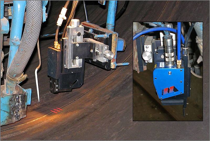
Photo: K.Willms, CC BY-SA 3.0, via Wikimedia Commons
This guide is aimed at industrial purchasing engineers and design engineers. It covers 6 chapters from working principle, scanner classification, sensing technologies, applications and measurement standards, spec-sheet decoding, to selection decisions, with 7 selection FAQs and manufacturer comparisons. Laser classification references the IEC 60825-1 standard; sensor performance figures reference published manufacturer datasheets from Keyence (LJ-X8000), Micro-Epsilon (scanCONTROL) and LMI Technologies (Gocator).
Chapter 1 / 06
What is a Laser Profiler
A laser profiler is an optical measurement head that captures the geometric cross-section of an object without touching it. The operating principle is laser triangulation: a laser diode and a line-generating lens spread the beam into a thin, static laser line that is projected onto the target. A receiving optical system images the diffusely reflected line onto a high-sensitivity 2D CMOS sensor matrix, mounted at a fixed angle to the projection axis. The controller then computes, for every illuminated column of the matrix, the lateral position along the line (the X axis) and the height of the surface at that point (the Z axis). The output of one exposure is therefore a complete profile: an ordered list of (X, Z) coordinate pairs describing a slice of the part.
This single-exposure profile is the defining trait. A conventional laser displacement sensor measures one distance value at one point; to obtain a cross-section it would have to be scanned along the part while a motion encoder tags each sample. A profiler captures the entire line at once, so width, gap, step height, radius, angle, and cross-section area can be derived directly from one frame. When relative motion is added, by moving the part on a conveyor or translating the sensor on a gantry, the stream of profiles assembles into a three-dimensional point cloud or height map. In this mode the scan-direction (Y) resolution is set by the part velocity divided by the profile rate, which is why profile rate matters as much as in-line resolution.
Structurally, an industrial profiler integrates four subsystems: (1) the illumination unit, a laser diode plus a Powell or cylindrical lens that produces a uniform-intensity line; (2) the receiving optics, a lens train arranged for the Scheimpflug condition so the tilted measurement plane stays in focus across the full depth; (3) the imager, a 2D CMOS array on which sub-pixel peak-detection algorithms locate the line centroid in each column; and (4) the controller, which converts raw pixel coordinates into calibrated millimetre coordinates, applies exposure control, and outputs data over GigE Vision, EtherCAT, or analog and digital I/O. In all-in-one smart sensors the measurement tools also run onboard.
The technology grew out of two streams. Laser triangulation displacement gauging was commercialised through the 1980s as laser diodes and CCD or CMOS arrays became affordable. Spreading the point into a line and reading a full row of the imager turned the point gauge into a profile gauge, and the rise of fast CMOS imagers and embedded processing after 2000 pushed profile rates from a few hundred hertz to well over ten kilohertz. Today the same physical principle scales across nine orders of dimensional magnitude, from micrometre solder-joint heights on a circuit board to road ruts measured by a vehicle at highway speed. No single head spans that range: the engineering task is matching the optical geometry to the part.
Four engineering metrics anchor profiler quality: Z measurement range, Z repeatability and linearity, X resolution and points per profile, and profile rate. These four interact through the optics. A wider Z range or X field of view trades against finer resolution, because the same imager pixels are spread over more millimetres. A higher profile rate may force shorter exposure and brighter laser power, which can raise the laser safety class. Understanding these trade-offs, not chasing any single headline number, is what makes a sound selection.
Chapter 2 / 06
Scanner Types and Configurations
Laser profilers split into families by what they output and how they integrate. The first axis is 2D versus 3D operation, the second is the controller architecture (separate controller versus all-in-one smart sensor), and the third is the optical geometry tuned for short, medium, or long working distance. The table below summarises the operating modes engineers encounter on datasheets and quotation requests.
Configuration
What It Outputs
Motion Needed
Typical Use
2D profile
One (X, Z) cross-section per exposure
None (static line)
Width, gap, step height, angle on a fixed station
3D scan (traversing)
Stacked profiles into a height map
Encoded conveyor or gantry
Full surface, volume, dent and weld bead mapping
All-in-one smart sensor
Profile plus onboard measurement result
Optional
Pass and fail decision at the sensor, no PC
Controller plus head
Calibrated profile to external controller
Optional
Multi-head systems, custom algorithms
Snapshot 3D sensor
Full area in one shot (not a moving line)
None
Static 3D of a whole part footprint
2D profile mode is the simplest deployment: the head and the part are both stationary, the laser line sits across the feature of interest, and each frame yields one cross-section. This is ideal for gauging the width of an extrusion, the gap and flush step between two car-body panels, the height of a glue bead, or the included angle of a machined chamfer. Because no motion system is required, 2D stations are inexpensive to commission and very fast, often running at the head's full profile rate as a continuous quality check.
3D scanning mode adds controlled relative motion. The part rides an encoded conveyor, or the sensor mounts on a linear axis or robot, and every profile is tagged with a Y position from the motion encoder. Stacking these slices reconstructs a height map of the whole surface, from which the system computes volume, dent depth, coplanarity, flatness, and full weld-seam geometry. The Y pitch equals belt speed divided by profile rate, so a head running 5 kHz over a belt moving 250 mm per second lays down a profile every 0.05 mm. Accurate, jitter-free motion encoding is as important to 3D accuracy as the optics themselves.
Smart sensor versus controller-plus-head is an integration choice. All-in-one smart sensors such as the Gocator family embed the laser, imager, and measurement engine in one housing and emit a pass-or-fail result or specific dimensions, needing no PC for routine operation. Controller-plus-head systems keep the optics in a compact head and send calibrated profiles to a separate controller or PC, which suits multi-head setups, very high data rates, or custom inspection algorithms. A related but distinct device is the laser snapshot 3D sensor, which captures an entire area in one exposure rather than sweeping a line, trading scan flexibility for instant whole-part capture on a static target.
The third axis, optical geometry, determines clearance distance and field width. Short-clearance heads sit close to the part and deliver the finest X resolution and Z repeatability over a narrow window. Long-clearance heads stand back, see a wide line, and tolerate hot or hazardous targets, at the cost of coarser resolution. Chapter 5 quantifies this trade-off across real model ranges.
Chapter 3 / 06
Red, Blue, and Sensing Technologies
Within the triangulation family, the most consequential technology choice is the laser wavelength, because it governs how the beam interacts with the surface. Red diodes near 660 nm are the long-standing default; blue-violet diodes near 405 nm have become the high-performance option for difficult materials. A minority of heads use near-infrared (NIR) sources around 808 nm for outdoor and road work. The table compares the practical engineering differences.
Why blue beats red on hard materials. Shorter-wavelength light penetrates less deeply into a surface before it scatters back. On translucent or organic materials, a red beam diffuses into the bulk and the reflected line widens and blurs, degrading the sub-pixel centroid and therefore Z resolution. The blue-violet line stays sharp on the surface of wood, food, semi-transparent plastics, silicone adhesive beads, and the specular edges of small electronic parts, producing cleaner edge data. Manufacturers report that blue technology hardly penetrates organic materials and images a crisp line where red struggles. The trade-offs are cost and safety class: blue heads are pricier, and for equal optical power a 405 nm beam is more hazardous to the eye, so blue models often carry a higher class than their red equivalents.
Glowing-hot targets. When inspecting red-hot forgings, billets, or extrusions, the part itself radiates strongly in the red and NIR band, swamping a red measuring laser. A 405 nm blue line is spectrally far from the thermal glow, so a narrow optical bandpass filter at the receiver passes the blue line and blocks the red-shifted self-emission. Blue laser profiling is therefore the standard answer for hot metal in steel and forging plants.
The sub-pixel sensing chain. Regardless of colour, the resolution-defining step is centroid detection. Each column of the CMOS matrix sees an intensity peak where the line crosses it; an algorithm fits that peak to fractions of a pixel, so calibrated Z resolution is finer than the raw pixel pitch would suggest. The receiving lens is tilted to satisfy the Scheimpflug condition, keeping the inclined measurement plane in focus across the whole depth of field. High dynamic range and multi-exposure modes (HDR) let one head handle a part that is matte in one region and shiny in another, by blending frames taken at different exposures.
Points per profile. The lateral sample count is set by how many imager columns are read out: representative figures are 1280 points on Gocator 2300 heads, up to 2048 on Micro-Epsilon scanCONTROL blue heads, and 3200 on Keyence LJ-X8000 heads. More points over the same field width means a finer X pitch and the ability to resolve narrower features, at the cost of more data to move and process. The right count is the one that places at least a few samples across your smallest feature, not the highest number on the page.
Chapter 4 / 06
Applications and Laser Safety Standards
Laser profilers earn their place wherever a dimension must be checked inline, at speed, without touching a moving or delicate part. The applications below recur across industries and define the spec envelope a head must meet.
Weld inspection and seam tracking: measuring weld bead height, width, and undercut, detecting the gap before welding, and steering the torch or ultrasonic probe along the seam in real time.
Gap and flush: the step (flush) and gap between adjacent body panels, doors, and trim on automotive assembly lines, a 100 percent inline check in modern plants.
Electronics and small parts: solder paste and bump height, connector pin coplanarity, and component placement, where blue-laser heads give the cleanest edges on shiny parts.
Adhesive and sealant beads: verifying that a glue or sealant bead is present, continuous, and the correct cross-section before assembly.
Tire, rail, and road: tire tread and sidewall profiling, rail and tram-rail wear documentation, and road surface surveys reporting rut depth, the International Roughness Index (IRI), and macro-texture.
General dimensional gauging: extrusion and rolled-profile cross-sections, machined step heights, flatness, coplanarity, and volume.
Because every profiler emits laser radiation, the governing safety framework is the international standard IEC 60825-1, Safety of laser products, which classifies products by the accessible emission and its potential to injure the eye or skin under normal and reasonably foreseeable use. National standards mirror it, including EN 60825-1 in Europe and the FDA 21 CFR 1040 scheme in the United States. The class printed on the head determines the engineering and administrative controls a site must apply.
Class
Description
Typical Profiler Use
Class 1
Safe under all normal use; no controls beyond labelling
Hazardous direct or specular beam; controls required
High-power and NIR road heads
Class 4
Hazardous including diffuse reflection and fire risk
Rare for profilers
Class 1 products are safe under all conditions of normal use and need only a label. Class 2 and 2M emit visible light at low power (the eye-safe definition sits near 1 mW for the relevant exposure), and the human aversion or blink response is assumed to limit exposure; a warning label suffices, but operators should still avoid staring into the beam. Class 3R covers roughly 1 to 5 mW continuous-wave beams whose power overpowers the blink reflex, so brief direct viewing can be hazardous and labelling plus operator awareness is required. Class 3B beams are hazardous on direct or specular reflection and demand engineering controls: restricted access, a key switch, interlocks, a remote interlock connector, and beam stops; near-infrared 808 nm road-scanning heads commonly fall here. Class 4, the most hazardous, is rare for profilers. The practical rule is to read the class off the datasheet, confirm it against your site laser safety officer rules, mount beam stops, and prevent specular reflections from returning toward operators.
On the dimensional side, profilers feed geometric quantities that are interpreted under geometric dimensioning and tolerancing standards such as ISO 1101 and ASME Y14.5, which define how flatness, profile of a surface, coplanarity, and angularity are specified and verified. For surface texture and roughness, the ISO 21920 series (which superseded ISO 4287 and ISO 4288) governs profile parameters, though dedicated contact and confocal instruments remain the references for sub-micrometre roughness. Knowing which standard the customer cites for the tolerance you are gauging keeps the measurement defensible.
Chapter 5 / 06
Key Specification Parameters
Reading a profiler datasheet is a fundamental skill. Different makers list 10 to 20 parameters, but a small set drives the selection: clearance (reference) distance, Z measurement range, X field of view and pitch, Z repeatability and linearity, points per profile, profile rate, laser wavelength and class, and interface. The comparison below uses published figures from three mainstream ranges to show how these specifications move together across the optical geometry; always confirm against the current datasheet for the exact model before purchase.
Spec (representative model)
Keyence LJ-X8020 (near)
Keyence LJ-X8400 (far)
Gocator 2320 (near)
scanCONTROL 30xx/BL
Reference / clearance distance
20 mm
380 mm
40 mm
25 / 50 mm range class
Z measurement range
±2.2 mm (4.4 mm)
±60 mm
25 mm
25 / 50 mm
X field of view
7 to 8 mm
180 to 240 mm
18 to 26 mm
~25 to 50 mm
Z repeatability
0.3 µm
5 µm
0.4 µm
single-micron class
Points per profile
3200
3200
1280
up to 2048
Laser / class
405 nm, Class 2M
405 nm, Class 2M
red, Class 2 / 3R
405 nm blue
Max profile rate
up to 16 kHz
up to 16 kHz
~170 to 5000 Hz
up to 10 kHz
Clearance (reference) distance and Z range. Clearance is the nominal standoff from the head face to the middle of the measurement window; Z range is the depth of that window. They scale together: the Keyence LJ-X8020 stands 20 mm off with a tight plus-or-minus 2.2 mm window, while the LJ-X8400 stands 380 mm off with a plus-or-minus 60 mm window. Pick a clearance that keeps the head clear of the part and any spatter or heat, then confirm the worst-case part height variation fits inside the Z range with margin.
X field of view and pitch. The field of view is the line length the head can read; X pitch is that width divided by the points per profile. A Gocator 2320 reads an 18 to 26 mm line with 1280 points, giving roughly 14 to 21 micrometre spacing, whereas a wide far-field head spreads its points over hundreds of millimetres and the pitch grows past a tenth of a millimetre. Ensure several samples land across your narrowest feature.
Z repeatability versus linearity. Repeatability Z is the random scatter of repeated height readings on a static flat target, often quoted at 95 percent confidence over thousands of frames: 0.3 micrometre on a close head, several micrometres on a long-range head, and as low as 0.2 micrometre on blue-laser precision sensors. Linearity (or accuracy) Z is the systematic deviation from true height across the range, usually a percent of Z range. They are independent; a head can be very repeatable yet bowed, so request both.
Profile rate. The profiles-per-second figure sets both the achievable 2D inspection throughput and, in 3D, the Y resolution at a given line speed. Heads span from roughly 170 Hz on legacy units to 10 kHz on blue scanCONTROL heads and up to 16 kHz on high-speed Keyence heads. Higher rates demand shorter exposure, which often needs more laser power or a more reflective target.
Laser, interface, and environment. Confirm wavelength (405 nm blue versus 660 nm red versus 808 nm NIR) against your material, and read the IEC 60825-1 class. Check the data interface (GigE Vision, EtherCAT, RS-422, analog and digital I/O) and the housing ingress protection, commonly IP65 to IP67 for shop-floor use, plus the operating temperature and any need for an air-purge or cooling jacket near hot processes.
Chapter 6 / 06
Selection Decision Factors
To turn the previous five chapters into a specific model, follow the decision sequence below. Most selection mistakes come not from a single wrong number but from deciding the wrong parameter first, for example fixing on a brand before confirming the part fits the Z range. These steps work as a fixed RFQ template.
Define the measurement and tolerance: state exactly what you measure (gap, step, bead height, full surface) and the tolerance, ideally citing the GD&T standard (ISO 1101 or ASME Y14.5). The required tolerance sets the repeatability and linearity you can accept.
Part size and standoff: the largest feature width sets the X field of view; the total height variation plus margin sets the Z range; obstructions, heat, and spatter set the minimum clearance distance.
Resolution and points: work back from the smallest feature. Ensure the X pitch (field of view divided by points per profile) places several samples across it, and that Z repeatability is a fraction of your Z tolerance.
Material and laser wavelength: opaque metal and ceramic suit a red head; wood, food, plastics, adhesive beads, glowing-hot metal, and shiny electronic edges call for a blue 405 nm head; outdoor road and rail may need an NIR head.
Speed and 3D resolution: for 2D, the profile rate sets throughput; for 3D, divide line speed by profile rate to confirm the Y pitch meets your need, and budget an encoded motion axis.
Laser safety class: confirm the IEC 60825-1 class (Class 2 or 2M, 3R, or 3B) is compatible with your site controls. Class 3B requires interlocks, restricted access, and beam stops.
Interface and integration: choose an all-in-one smart sensor for a self-contained pass and fail station, or a controller-plus-head for multi-head systems and custom algorithms. Confirm GigE Vision, EtherCAT, or analog and digital I/O fit the PLC or PC.
Environment and protection: ingress protection (IP65 to IP67), operating temperature, vibration, and whether air-purge or a cooling jacket is needed near hot or dusty processes.
One last dimension that buyers overlook is manufacturer serviceability and software: the quality of the measurement and setup software, availability of measurement tools onboard the sensor, calibration certificate traceability, firmware updates, local technical support, and spare-part lead time. A profiler is a system, not just optics, and the software often decides how fast a line is commissioned and how easily it is retuned years later. Keyence, Micro-Epsilon, LMI Technologies (Gocator), Cognex, SICK, and Wenglor maintain regional support and calibration in China, which makes them defensible choices for large projects, while Hokuyo and Riftek serve cost-sensitive and specialised niches.
FAQ
What is the difference between a laser profiler and a laser displacement sensor?
A laser displacement sensor projects a single point and returns one distance value (Z) per sample. A laser profiler projects a laser line and returns a full cross-section: hundreds to thousands of (X, Z) coordinate pairs along that line in a single exposure. A profiler is effectively a row of displacement points captured simultaneously. This lets a profiler measure width, gap, step height, radius, angle, and cross-section area in one shot, whereas a point sensor would need scanning plus precise motion encoding to reconstruct the same profile. Profilers cost more and demand more processing, but eliminate one axis of mechanical motion.
How does laser triangulation work in a profile scanner?
A laser diode plus a line-generating (Powell) lens projects a thin laser line onto the target. The diffusely reflected light is imaged through a receiving lens onto a 2D CMOS matrix at a fixed triangulation angle. The position of each illuminated pixel column on the matrix encodes the height (Z) at that point along the line, while the pixel row encodes the lateral position (X). The controller runs sub-pixel peak detection on every column, typically delivering Z resolution far finer than the camera pixel pitch. Larger triangulation angles and longer baselines raise Z resolution but shrink the usable measurement range and increase occlusion.
When should I choose a blue laser instead of a red laser profiler?
Blue-violet lasers (around 405 nm) have a shorter wavelength than red lasers (around 660 nm), so the beam penetrates less into the surface and scatters less inside translucent or organic materials. Choose blue for red-hot glowing metal (the blue line stays visible against red-shifted thermal radiation), for wood, food, adhesive beads, plastics, and semi-transparent objects, and where the sharpest possible line is needed on specular edges in electronics inspection. Red lasers remain the cost-effective default for opaque metal, ceramic, and general parts. Blue-laser models cost more and often carry a higher laser class for the same optical power.
What do profile rate, points per profile, and X pitch mean on a datasheet?
Points per profile is how many (X, Z) coordinate pairs one laser line yields, commonly 1280, 2048, or 3200. X pitch (data interval) is the lateral spacing between adjacent points: field-of-view width divided by point count, ranging from a few micrometers near field to over 1 mm on wide far-field heads. Profile rate (Hz) is how many complete profiles per second the head outputs, from roughly 170 Hz on legacy units to 16 kHz and beyond on high-speed inline heads. For 3D scans, scan-direction (Y) pitch equals conveyor speed divided by profile rate, so a high profile rate is what allows fine Y resolution at production line speed.
How do I read Z range, Z resolution, linearity, and repeatability?
Z range (measurement range) is the depth window the head can see, for example plus-or-minus 2.2 mm near field up to plus-or-minus 60 mm far field. Repeatability Z is the random scatter of repeated height readings on a static flat target, often quoted at a 95 percent confidence over thousands of frames, from 0.3 micrometer on close heads to several micrometers on long-range heads. Linearity (or accuracy) Z is the maximum deviation from the true height across the full range, usually a percent of Z range. These are independent specifications: a head can be very repeatable yet non-linear, so do not collapse them into one accuracy number.
What laser safety class do profilers use and what does it require?
Industrial profilers are classified per IEC 60825-1. Most low-power heads are Class 2 or 2M (visible, under 1 mW accessible in the eye-safe definition, protected by the blink reflex) and need only a warning label. Higher-power or blue heads are often Class 3R (1 to 5 mW, beam exceeds the blink-reflex protection) or Class 3B, which require trained operators, restricted access, a key switch or interlock, and a remote interlock connector. NIR 808 nm road-scanning heads can reach Class 3B. Always match the installed class to your site laser safety officer rules, mount beam stops, and avoid specular reflections back toward operators.
Which manufacturers and series should I shortlist for a laser profiler?
Keyence (LJ-X8000 series, 3200 points per profile, 405 nm) suits high-resolution inline gauging with turnkey software. Micro-Epsilon scanCONTROL (25xx, 29xx, 30xx, including blue-laser BL variants up to 2048 points and 10 kHz) covers precision profile and welding tasks. LMI Technologies Gocator (2300, 2400, blue-laser 2410 and 2420 down to 0.2 micrometer Z repeatability and 6 micrometer X resolution) are all-in-one smart sensors with onboard measurement. Cognex, SICK, Wenglor, Hokuyo, and Riftek also serve this space. Match clearance distance, Z range, X resolution, and profile rate to the part, then confirm laser class and software fit.