
A conventional angular contact ball bearing supports combined radial and one-directional axial loads, whereas an angular contact thrust ball bearing is selected when axial stiffness and thrust capacity dominate the duty cycle [S1][S2].
The comparison is a complete-arrangement decision covering load direction, contact angle, preload, speed, moment loading, lubrication, and support spacing, not a simple comparison of catalogue thrust ratings [S1].
Load Path and Geometry Define the Choice
An angular contact ball bearing has offset inner- and outer-ring raceways, producing an inclined line of action that lets the rolling elements carry radial and axial forces together [S1][S2]. A conventional single-row unit supports axial load in one direction, so two or more bearings are required when thrust can act in both directions [S2].
Typical contact angles include 15°, 25°, 30°, and 40° [S4]. A larger contact angle generally raises axial capacity while reducing the radial-load share; a smaller angle favors radial loading [S1][S4]. The selection guide for 15°, 25° or 40° angular contact bearings provides a more detailed treatment of that tradeoff.
An angular contact thrust ball bearing uses a more strongly axial-oriented contact geometry to concentrate capacity along the shaft axis [S1]. It is not simply a radial bearing with a different housing. The complete support arrangement must still control radial reaction, overturning moment, shaft alignment, and thermal growth.
Decision Criteria: Load, Stiffness, Speed, and Installation
The primary comparison is axial load versus radial load. Angular contact ball bearings are generally preferred when radial force is substantial and axial force is also present. Angular contact thrust ball bearings become more appropriate when thrust is the dominant load and the mechanism needs a stiff, accurately located axial support [S1].
The second criterion is moment capacity. A conventional angular contact bearing handles combined loads, but an isolated bearing still has a limited load-center span. Duplex arrangements extend that span: a DB, or back-to-back, pair provides greater effective support spacing and high moment rigidity, while a DF, or face-to-face, pair has closer load centers and tolerates more misalignment [S1][S4].
The third criterion is radial-load capacity. Increasing contact angle improves axial capacity but lowers radial capacity [S4]. An angular contact thrust bearing should not be selected on axial capacity alone if radial reaction is high; otherwise the raceways, balls, cage, and lubrication system may be loaded outside the intended duty.
The fourth criterion is installation complexity. A single angular contact bearing is simpler for one-way axial loading. Duplex angular contact bearings add pairing, preload control, matching, and correct orientation requirements. A thrust-oriented design can simplify the primary axial reaction, but it does not eliminate the need to react other forces [S1][S2].
Duplex Arrangements for Bidirectional or High-Moment Duty
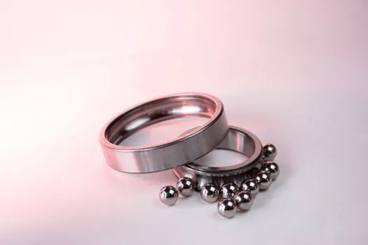
DB angular contact bearings carry axial load in either direction, with each direction assigned to one bearing, while their wide load-center spacing increases resistance to overturning moments [S4]. The back-to-back arrangement is therefore a stronger candidate for machine-tool axes and other applications where shaft bending or tilting moment can control the design.
DF angular contact bearings also carry bidirectional axial load, but their shorter load-center spacing reduces moment capacity and improves tolerance of slight misalignment [S4]. A DT, or tandem, arrangement places bearings in series to increase axial capacity in one direction. It should not be treated as a bidirectional support unless the shaft geometry and bearing orientation independently prevent reversal of the thrust [S1][S4].
For a one-direction thrust application, the detailed logic in Tandem Angular Contact Bearing Arrangement: When One-Direction Thrust Needs a Stacked Pair separates axial-capacity stacking from the wider combined-load function of a DB or DF pair.
Preload Changes System Behavior, Not Just Clearance
Axial preload introduces rolling-element forces before the external load reaches the bearing, reducing internal clearance and improving rotational accuracy and stiffness. The added force also increases heat generation and can shorten service life if preload is excessive [S1][S4].
Preload selection must therefore be tied to the actual load spectrum rather than copied from a generic bearing table [S1]. Catalogue ratings describe capacity under defined rating conditions, but installed performance also depends on operating temperature, lubrication, fitting, shaft stiffness, housing stiffness, and the direction and sequence of applied load [S1].
Ball-screw support illustrates the distinction. Angular contact bearings can carry axial and radial loads while providing precise shaft location, which makes a duplex arrangement a common solution for a screw drive exposed to both forces [S3]. An angular contact thrust ball bearing is the stronger candidate when axial stiffness and thrust capacity dominate the design, but the radial reaction must remain compatible with the selected geometry [S1].
Application Fit and Failure Modes

Angular contact ball bearings are broadly suited to machine-tool spindles, pumps, compressors, motors, elevators, and precision transmissions because they combine radial support with controlled one-direction axial capacity [S4]. Miniature angular contact bearings, commonly described as having bores below 10 mm, address space-constrained and precision-critical assemblies [S4].
Angular contact thrust ball bearings are more appropriate for precision supports where axial force is dominant, including ball-screw supports, rotary positioning systems, and compact mechanisms that need high axial stiffness [S1]. They are less suitable where substantial radial loading requires a conventional angular contact bearing or another radial-capable support.
Common failure mechanisms include excessive heat, preload loss, vibration, inaccurate positioning, and premature bearing failure [S1]. Selection errors include treating a thrust bearing as a radial-load bearing, choosing only by outside diameter, ignoring moment load, and using catalogue ratings without operating conditions [S1]. Bore diameter, outside diameter, width, and mounting envelope still constrain feasibility, but none alone determines the load capacity.
Selection Method for Procurement and Testing
Begin with the real load spectrum, including radial force, axial force in each direction, shock, speed, duty cycle, temperature, and required service life [S1]. Then document the support spacing and identify whether overturning moment is created by the applied force, shaft deflection, or housing distortion.
Compare candidate bearings at the same bore and mounting envelope where possible. Use the applicable manufacturer catalogue for dynamic and static ratings, limiting speed, axial and radial load factors, internal clearance, preload method, and lubrication requirement. The published guidance identifies contact angle, ball size and count, bearing material, design, cage, and operating conditions as contributors to actual performance [S1][S5].
Verify the complete arrangement before release. Confirm bearing orientation, pairing or matching, preload method, shaft and housing fit, seal or shield type, lubricant, installation procedure, and the protection scheme against contamination. For metrology-grade selection, distinguish ISO or ABEC dimensional and running-accuracy classes rather than treating them as interchangeable [S5].
Selection Rules for Precision and Combined-Load Mechanisms
Choose a conventional angular contact ball bearing when radial and axial loads are both material, when a duplex arrangement can control bidirectional thrust and moment, or when the shaft requires a flexible combined-load support [S1][S2]. Choose an angular contact thrust ball bearing when axial stiffness and thrust capacity are the controlling requirements and radial reaction remains within the product's intended duty [S1].
The practical test is simple. If removing the radial-load share would still leave the bearing correctly loaded for the application, the thrust-oriented design deserves evaluation. If removing it would fundamentally change the load path, specify an angular contact bearing or a thrust bearing paired with a separate radial support. The final choice must be confirmed against manufacturer catalog data and the complete machine load case, not by type name alone.