
Autocollimation is the most precise purely optical method to verify that a mirror face is square to a line of sight: a telescope focused at infinity emits a collimated beam, a flat mirror returns it along the same path, and any tilt of the mirror offsets the reflected reticle image by exactly twice the angular error, which is then read against the theodolite's graduated circles [S2]. For machine axis alignment, the same geometry is used to check the squareness of linear slides, the perpendicularity of horizontal bores to vertical spindles, and the pitch/yaw of rotary tables against a reference mirror fixed to the moving member.
On a one-second theodolite, the direct angular readout is 1 arc-second (≈4.85 µrad), and the autocollimated return image resolves to roughly the same order because the displacement of the crosslines is read against the same graduated circle [S2]. Industrial alignment packages built around theodolite instruments routinely reach ±0.5 arc-second repeatability when the mirror is mounted on a kinematic seat and the room is thermally stabilised, a figure consistent with the autocollimation alignment chains documented for large ground-based telescopes [S1][S2].
How the autocollimation geometry produces an angle reading
When the line of sight is perpendicular to a flat mirror, the reflected image of the illuminated reticle forms in the plane of the reticle itself, perfectly superimposed on the original crosslines; any non-perpendicularity between the optical axis and the mirror face displaces the return image by an angle equal to twice the mirror tilt, which is why the method is sensitive to angular error rather than linear position [S2]. A second target printed on the cover glass, the displacement target, is used to measure lateral offset of the mirror along the beam, but only for stand-off distances under 20 m, beyond which the geometry of the cover-glass reticle breaks down [S2].
The standard sighting chain pairs the theodolite with a flat or pentaprism target mounted on the moving machine element. For pure squareness checks, the flat is sufficient; if the engineer needs the actual tilt value, a separate collimator is inserted in the line of sight and the tilt target is read in minutes of arc, independent of the theodolite's own scale [S2]. This separation between squareness measurement (autocollimation on a flat) and tilt measurement (collimator with tilt target) is the first design decision a metrology lead has to lock in before the alignment crew arrives on site.
Spec tiers: one-second optical vs electronic theodolites for axis work
The ESO 3.6 m telescope maintenance manual specifies a "one-second theodolite" as the workhorse for the alignment facility, used for perpendicularity checks between the alpha and delta axes, between the delta and tube axis, and for setting the top-end units and primary mirrors, with sighting-telescope autocollimation reserved for the more critical runs [S2]. A one-second theodolite offers direct circle reading to 1" and estimation to 0.1", which translates to a worst-case angular error of about 5 µrad at the mirror.
Electronic theodolites, also called total stations in their survey-grade form, replace the glass circle and vernier with an absolute encoder read by an LCD; common industrial-class encoders deliver 1" or 2" angular resolution with dual-axis tilt compensation, and the data is exported over RS-232 for the spatial-analyzer software stack used to merge theodolite, laser tracker, and laser radar into a single best-fit coordinate frame [S1]. The practical difference for a machine-axis job is throughput: a one-second optical instrument with a skilled operator will resolve about 0.5" of squareness, while a 1" electronic instrument with on-board averaging and tilt sensor will reach the same number in a third of the operator time, at the cost of needing power and a data cable at the instrument station. Selection between the two comes down to distance, vibration, and whether the data must feed a downstream best-fit fit (laser tracker, spatial analyser) or stand alone as a paper log.
Typical alignment setups for machine tool and large-rotor axes
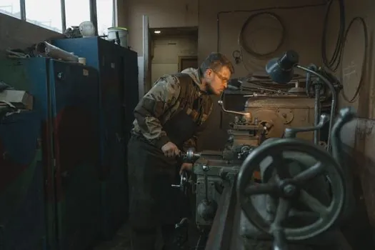
The four classical configurations seen on machine axis jobs are: (1) theodolite plus flat mirror on a magnetic base, used to set a linear axis parallel to a reference datum; (2) two theodolites autocollimating to a common pentaprism to establish a horizontal reference plane, with the machine's vertical bores checked against that plane; (3) a single theodolite plus an electronic autocollimator for high-resolution squareness between a spindle axis and a slide; and (4) theodolite, laser tracker, and laser radar tied into a common coordinate frame through a best-fit transform, used when the alignment tolerance is below 0.1 mm over a 10+ m envelope [S1].
For machine tool builders, the one-second theodolite plus a kinematic flat is still the reference method for setting a grinding machine's slide to within 0.01 mm/m of straightness, and for verifying that a vertical spindle is square to the table within 0.005 mm/300 mm. For large rotors and telescope axes, the autocollimation chain typically goes through a pair of flats on opposite sides of the rotor and a sighting telescope, with the one-second theodolite used to cross-check between stations; the metrology-based alignment of the OSIRIS-REx OVIRS spectrometer documents exactly this combination of laser tracker, laser radar, theodolite, and spatial-analyser best-fit for large optical benches [S1].
Selection criteria: who it is for, who it is not
An autocollimation theodolite is the right tool when the tolerance is expressed in arc-seconds or in linear units that convert to arc-seconds at the working distance, when the working distance is between 1 m and 50 m, when the environment is dim or can be shaded, and when the alignment has to be done by a metrology technician rather than a machine operator. It is the wrong tool for sub-arcsecond squareness over short stand-off (use an electronic autocollimator with a 0.1" resolution head), for alignments inside a sealed machine envelope where the line of sight is obstructed (use a laser tracker with an SMR or a laser interferometer), or for outdoor construction tolerances that can be met with a one-millimetre total station and don't justify the operator cost of a one-second theodolite [S1].
A practical decision rule: if the required squareness at the workpiece is tighter than 0.02 mm/100 mm (about 40 arc-seconds), start with a one-second theodolite plus flat; if it is tighter than 0.002 mm/100 mm (about 4 arc-seconds), step up to an electronic theodolite with a calibrated autocollimation eyepiece and a thermal-stable mirror mount; if it is tighter than 0.0002 mm/100 mm (about 0.4 arc-seconds), move to an electronic autocollimator or a laser interferometer with a flat reference, and use the theodolite only for gross pre-alignment of the interferometer beam [S1][S2].
Failure modes and environmental limits
The most common field failure is operator-induced: a dirty or scratched flat mirror turns the return image into a fuzzy blob, and the crosslines can no longer be read to the limit of the theodolite's scale. The second most common failure is thermal: a theodolite set up across a sunlit bay will have a line of sight that wanders by tens of arc-seconds over a five-minute interval as the aluminium tripod warms asymmetrically, which is why large-telescope alignment work is done at night with the domes at thermal equilibrium [S2]. The third failure mode is collimation drift: the telescope's own optical axis is not perpendicular to the trunnion axis, so the autocollimated return image has a built-in offset that has to be removed by a two-face reading on the mirror, with the mean of the two face-left and face-right readings cancelling the instrument collimation error.
Atmospheric shimmer and side-scatter are the practical stand-off limit. Over 30 m of warm air, even a well-collimated one-second theodolite will see the return image boil by 1–2 arc-seconds, which is why the displacement-target method on the cover glass is restricted to under 20 m [S2]. Vibration from a nearby press or a forklift aisle will smear the return image similarly; the cure is to read at night or behind a hanging curtain, and to time the reading between machine strokes.
Sourcing, standards, and the role of a theodolite reference
There is no single ISO or IEC standard that governs "autocollimation theodolite" as a product; the relevant metrology practice is ISO 17123 (optics and optical instruments, field procedures for testing geodetic and surveying instruments), and the angular accuracy convention itself is documented in the vendor datasheets as "DIN 18723" or "ISO 17123-3" one-second class. For an engineering buyer the spec to compare across vendors is the angular accuracy in arc-seconds under ISO 17123-3 testing, the smallest displayed increment (0.5" or 1"), the reticle pattern (crossline or crossline-plus-tilt-target), and the availability of a calibrated electronic autocollimation eyepiece for higher-resolution runs [S1][S2].
For routine machine-axis jobs, a one-second optical theodolite from a metrology-rental house remains the cheapest reliable answer; for repeated high-volume alignment cells, a 1" electronic theodolite with data export into a spatial-analyser best-fit framework is the modern default, and the laser tracker is added only when the envelope exceeds the theodolite's practical stand-off [S1]. The next signal worth tracking is the spread of wireless, Bluetooth-tethered electronic theodolites that broadcast angular readings directly to a tablet running the spatial-analyzer best-fit, which removes the operator's manual transcription step and tightens the repeatability on production alignment cells. The related question of how an instrument's optical versus electronic angle readout actually works is laid out in Optical vs Digital Theodolite Reading Methods: How Angle Readout Actually Works, which pairs naturally with this article for any engineer buying into a new alignment cell in 2026.