These couplings fit servo axes, CNC machinery, robots, packaging equipment, conveyors, shredders and other drives where repeatable overload separation, adjustable torque and controlled reset behavior matter [S3][S4].
How ball-detent overload separation works
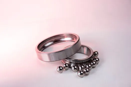
Ball-detent torque limiters use precision-hardened steel balls seated in conical detents and held against their seats by spring force [S2]. During normal operation, the balls constrain two coupling halves so they rotate as one unit and transmit torque [S3].
When transmitted torque exceeds the calibrated limit, spring preload is overcome, the balls roll out of the detents, and the driving and driven sides separate [S3]. Full-disengagement designs push the balls axially clear and can require a plunger-operated reset rather than automatic re-engagement [S4].
Repeated setting accuracy is also design-dependent: a precision ball-detent limiter has been described as maintaining approximately ±5%, compared with roughly ±20% for a shear-pin arrangement [S8].
Selecting a reset mode for the driven machine
Multi-position reset uses equally spaced detents, allowing the balls to enter the next detent after the overload is removed and enabling rapid restart without preserving the original angular relationship between shafts [S3].
Single-position reset uses asymmetrically or randomly arranged detents, so re-engagement occurs only when the driving and driven members return to their original relative positions [S3]. This preserves synchronization, but the operator cannot reset the mechanism at an arbitrary shaft angle [S3].
Full-disengagement versions provide a third practical choice: the coupling remains separated until an axial plunger action re-engages the torque module [S4]. The selection criterion is therefore operational, not merely electrical: rapid recovery, phase retention, or deliberate lockout should follow the restart consequence of the machine.
Multi-position reset trades speed for wear
Multi-position reset gives the shortest recovery path because each ball can settle into the next detent after the jam is cleared [S3]. The same design can continue to trip or ratchet while the overload remains, producing continuing wear on the plates and detents [S3].
Single-position reset reduces arbitrary repeated engagement because the members must return to their original relative positions before the balls can seat again [S3]. That makes it more suitable where controlled phasing or synchronization is a process requirement rather than an optional convenience [S3].
Many designs also include a non-driven-side plate movement that actuates a mechanical switch or proximity sensor, allowing the system to alert the operator or remove drive power after separation [S3]. The electrical indication must therefore be designed as part of the protection sequence, not treated as a substitute for mechanical isolation.
Ball detent versus shear pin and electronic protection
Ball-detent limiters are intended for repeatable preset-torque separation, while shear pins provide a simpler sacrificial overload element with materially wider setting variation, approximately ±20% in the cited comparison [S8]. The ball-detent mechanism reaches a stated ±5% accuracy class in that comparison [S8].
The practical comparison is therefore: ball detent for fast, adjustable and repeatable torque separation; shear pin for a sacrificial, coarse-trip arrangement; electronic limiting for operating control and diagnostics; and permanent-magnet or sprag engagement for other torque-control functions that are not equivalent to jam isolation [S3].
Torque capacity, geometry and installation constraints

Transmittable torque depends on the number of torque modules and their radius from the coupling center [S4]. One heavy-duty ST family covers 1,000–160,000 N·m and uses spring-loaded ball detents for full disengagement [S4].
The published ST series covers a torque-limiter family with a stated range of 1,000–160,000 N·m [S4].
Model selection therefore cannot be reduced to rated torque alone. Bore range, flange geometry, module count, radial spacing, reset method and required coupling performance must be checked together [S4]. The adjustable housing and plunger core provide a visible torque scale, while sealed torque modules are intended to limit contamination by dirt and debris [S4].
Applications where mechanical isolation earns its place
Ball-detent limiters are common on servo-driven machine-tool axes, woodworking machinery, robots and packaging machines, where a jam can propagate shock through the driven train [S3]. Heavy-duty ST applications include rolling mills, dredgers, steel mills, industrial shredders and industrial conveyors [S4].
The device is not a universal substitute for overload protection. A torque limiter specifically addresses torque overload, jams, collisions and sudden load spikes, but it does not cover unrelated failure modes [S6]. It also does not correct an undersized motor, a defective bearing, a misaligned shaft or a process obstruction that remains after restart.
Before installing one, confirm that the coupling bore suits the shaft, that the selected adjustment range contains the required trip torque, and that the mechanism has sufficient axial clearance for separation. The application must also define whether reset is manual, single-position, multi-position or externally signaled, because each mode changes restart time, synchronization and operator procedure [S3][S4].
Commissioning and evidence of correct protection

Commissioning should verify the adjusted trip torque, ball travel, complete separation, indicator operation and reset sequence rather than infer protection from a catalog rating [S2][S4]. A controlled obstruction test can reveal whether the limiter actually separates the shafts within the equipment’s risk assessment and whether downstream components remain isolated after the trip [S1].
Track at least three service variables after installation: number of trips, time between trips, and visible wear on the detent and coupling plates. Repeated multi-position ratcheting after an uncleared jam is itself an indication that the obstruction or process fault remains, not merely that the limiter needs adjustment [S3].
The next verification point is a documented overload test at the production operating point, including sensor indication, motor-stop behavior and the selected reset procedure. That record closes the gap between an installed coupling and demonstrated jam protection.