
Vertical ball screw assemblies normally require paired angular-contact bearings to carry gravity and reversing axial loads, while horizontal shafts usually use one fixed support and one floating support to minimize thermal growth.
The mounting decision must cover screw diameter, lead, travel, load direction, lubrication, preload and housing rigidity, because bearing orientation alone does not make a vertical screw system suitable for a horizontal machine or vice versa.
Mounting architecture and load direction
A ball screw converts rotary motion into linear motion through recirculating steel balls running between the screw and nut threads.
For a horizontal screw, gravity does not produce a continuous axial load on the nut. The support arrangement therefore normally separates axial location from thermal expansion: one end constrains axial movement, while the other permits controlled movement along the screw. This arrangement is appropriate when radial loads are modest and alignment can be held within the bearing system requirements.
For a vertical screw, the translating table, nut and attached tooling impose a continuous axial load, and the direction reverses during up and down motion. A single deep-groove or thrust bearing arrangement is generally less suitable because it does not provide the same combined axial and radial support as a properly arranged angular-contact pair. The ball screw itself should be selected from its rated axial load, speed, lead and accuracy, not from mounting orientation alone.
Horizontal mounting: fixed end and floating end
A horizontal installation should use a fixed-end bearing group and a floating-end bearing group. The fixed group controls axial position, while the floating group permits expansion caused by screw and nut heating. Both groups still need enough radial support for the screw, and the housing must resist the reaction from the applied axial force. [S3]
Lintech’s technical information lists the RS, PS, and GS Series, with RS Series models shown in diameter ranges from 0.500–0.750 inches, greater than 1.000 inches, and 1.500 inches.
The fixed bearing arrangement is normally the more precisely located end, while the floating arrangement controls thermal movement rather than adding unnecessary axial stiffness. Over-constraining both ends can generate preload growth, heat and premature wear. The thrust bearing approach is appropriate where the fixed end must carry substantial axial force, but it must be paired with suitable radial support and a defined axial-locking method.
Vertical mounting: thrust path and paired support
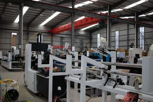
A vertical axis must carry the weight of the table and tooling in addition to machining thrust. The same mechanical checks apply to a vertical ball screw support arrangement.
Paired angular-contact bearings are the normal high-load solution because their asymmetric geometry supports axial and radial forces while maintaining positive shaft location. For a triplex arrangement, the load is distributed across three bearings and preload must be controlled as a system, not applied to one bearing independently. A field report states that ball-screw bearing preload is usually set mechanically with spacers inside the assembly and that tightening torque ranges from 50–150 ft-lb depending on screw size and other factors.
The lower arrangement must maintain axial location without over-constraining the screw. In a vertical installation, gravity can conceal free play because the load direction removes the gap; check movement with a dial indicator and verify that the housing shoulder, locknut and cover capture the bearing rings as intended [S5].
Bearing options compared by installation criteria
Angular-contact bearings, deep-groove bearings and dedicated thrust bearings solve different load problems. Angular-contact bearings provide the strongest case for a vertical axis with reversing axial load and useful radial support. Deep-groove ball bearings are more appropriate where radial load dominates and axial requirements are limited. A thrust bearing is efficient for predominantly axial loading, but it normally needs a separate radial support, so the total assembly may cost more in space and parts than a correctly selected angular-contact pair. [S5]
Angular-contact ball bearings use asymmetric race geometry, so the wider outer-race section identifies the thrust-loaded side. The contact angle also differs from that of a general spindle bearing, and the arrangement must match the selected bearing designation rather than a generic 15, 25 or 40 degree assumption [S5]. The distinction between an angular contact bearing and a deep-groove bearing is especially important when sizing capacity, preload and axial play.
For horizontal shafts with low axial load, the low-complexity option is a fixed deep-groove or angular-contact bearing combined with a floating radial bearing. For vertical screws under reversing axial load, use a matched angular-contact arrangement with controlled preload and axial retention. For very high axial load with negligible radial load, a dedicated thrust bearing plus a radial support remains valid, but the mechanical arrangement must justify the extra components.
Preload, thermal growth and installation errors

Preload must be applied by the bearing manufacturer’s specified method, using force, displacement or strain rather than an arbitrary tightening torque. One bearing example used a 4,500 N preload with a starting torque of 0.33 N-m, but discussion correctly identified that preload force cannot be converted into a universal nut torque without screw diameter, pitch and efficiency [S3].
Axially ground angular-contact bearings can be arranged so the inner races contact under the specified preload and the locknut cannot increase preload beyond that controlled contact condition. Other designs use measured spacers or screw stretch. Mechanical spacers are common, while one installation range for preloaded bearings was given as 50 to 150 ft-lb depending on screw size and bearing arrangement; this is a tightening range, not a universal preload specification [S3].
Vertical systems also require lubrication retention, contamination exclusion and suitable seals. Horizontal systems still require a defined path for lubricant to reach the screw and return path for the nut. A vertical nut can drain or retain lubricant differently, and an upward or downward screw changes where debris accumulates. These effects alter lubrication interval and inspection frequency even when the bearing arrangement remains unchanged.
Selection checks by axis and use case
Horizontal installations suit linear slides, gantries and machine tools where axial load is light to moderate, thermal expansion is the dominant sizing issue and a fixed-plus-floating support can be aligned accurately. The selected ball screw should still meet the required lead, repeatability and speed. Lintech lists maximum travel examples of 67 inch, or 1,702 mm, for RS Series 0.500 inch diameters; 73 inch, or 1,854 mm, for PS Series 0.625 inch and 16 mm diameters; and 40 inch, or 1,016 mm, for GS Series 0.625 inch and 16 mm diameters [S1].
Vertical installations suit machining centers, routers, lift axes and presses where the table or tool applies reversing axial force. These systems should use paired angular contacts where both axial capacity and radial stiffness are required, then specify preload, locking and lubrication from the machine and bearing manufacturers. LINTECH identifies ball screws as the lead-screw choice for high-duty-cycle, high-speed and long-life applications, but that general suitability does not remove the need to size the screw and bearings for the actual vertical load [S1].
Do not convert a horizontal bearing set by simply rotating the housing. Check the bearing axial-load rating against table and tooling weight, confirm that the locking arrangement carries the sustained thrust, verify lubricant retention and ingress protection, and test axial play under controlled load. A trial installation should also record screw stretch or indicator movement, because a vertical axis can conceal a loose bearing stack that appears acceptable under gravity alone [S3][S5].
For procurement, specify axis orientation, shaft-up or shaft-down arrangement, supported mass, working and peak axial load, reversing-load duty, screw diameter and lead, travel, accuracy target, lubrication method, sealing requirement, housing material, preload method and the required axial lock. These parameters allow the bearing supplier and machine builder to distinguish a correctly supported vertical thrust package from a horizontal support set that has merely been turned 90 degrees.