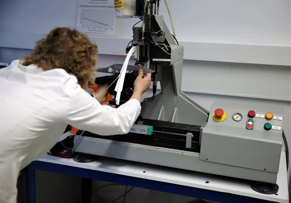
Ball screw accuracy grades define permissible travel deviation over a 300 mm reference length, with C0 through C10 spanning positioning and transport applications [S2].
The critical distinction is that the ν300 deviation range must not accumulate over the screw length for positioning screws, while transport screws may permit accumulation [S1].
What the 300 mm Lead Error Specification Means
ν300 is the maximum peak-to-valley range of travel deviation measured over any 300 mm section of the useful screw length, and it is the most commonly used definition of lead accuracy [S1]. The reference distance is 300 mm, not the total stroke, so a 900 mm axis is not assigned a single 900 mm error simply by multiplying the 300 mm limit by three.
Lead error also has a mean component. The difference between expected travel and actual travel can be expressed as an actual mean travel deviation, while the sum of individual deviations is represented by Σe = E [S3]. A travel deviation diagram records these characteristics as actual travel against the expected travel amount [S4].
For positioning screws, the distinction matters mechanically. The ν300 range is not permitted to accumulate over the useful length, whereas it may accumulate for transport screws [S1]. This makes ν300 a useful specification for axes where position must remain controlled, but it is not a complete substitute for examining the entire travel curve, especially when the stroke is shorter than 300 mm.
How Accuracy Grades Change the Selection
JIS B 1192 and ISO 3408 establish accuracy terminology for ball screws, with C0 to C5 based on linearity and directional properties and C7 to C10 based on travel-distance error relative to 300 mm [S2]. JIS uses C for positioning screws and Ct for transport screws, while DIN and ISO use P and T, respectively [S1]. Lower numerical grades permit smaller deviations and therefore provide higher accuracy.
THK states that accuracy grades C0 to C5 are defined in terms of linearity and directional property [S2]. THK states that accuracy grades C7 to C10 are defined in terms of travel distance error in relation to 300 mm [S2]. These values are grade and effective-length dependent, so the exact table entry must be checked rather than treated as a universal grade number.
A practical comparison is therefore straightforward: C0 to C5 support precision positioning and are evaluated with representative travel error, fluctuation over 300 mm and fluctuation over one revolution; C7 to C10 are intended for transport duties and use travel-distance error over 300 mm [S2]. For an axis that must stop accurately at multiple points, the C-grade and one-revolution data deserve more attention than a transport-grade specification alone.
Where 300 mm Error Becomes Misleading
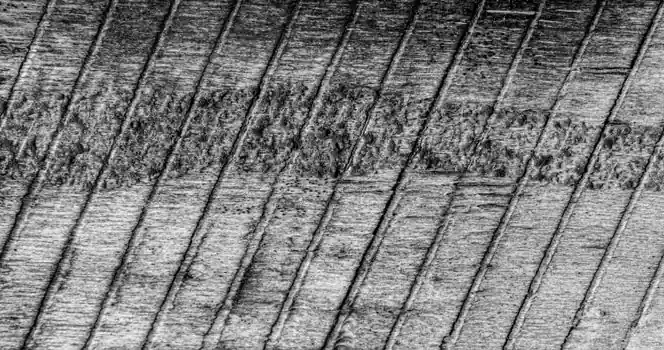
When the stroke is less than 300 mm, the ν300 specification may not describe the error that matters most to the application. A typical P5 screw can show 8 μm lead error per revolution, equal to one third of its 23 μm allowable error over 300 mm [S5]. The per-revolution error produces short-scale wobble, often called ball screw drunkenness, that can impair motion quality even when the catalogued 300 mm value is satisfied [S5].
The relationship between lead and travel illustrates the issue. A 2 mm lead screw with 100 mm travel is expected to move 100 mm after 50 revolutions, but actual travel may be 99.980 mm or 100.025 mm because of component and manufacturing deviations [S4]. The difference from the expected 100.000 mm is the actual mean travel deviation, while the variation within the travel curve must also be checked over 300 mm and one revolution [S4].
S5 supports continuous measurement that records positional accuracy throughout full travel rather than relying only on individual measurements [S5]. The correct design response is not to reject every 300 mm specification, but to specify one-revolution error, cumulative lead error and the applicable stroke-length band, then verify the assembly under load and at operating temperature.
Positioning, Transport and Application Fit
Positioning screws are intended for controlled point-to-point movement, while transport screws are intended to move material or loads where continuous motion is more important than precise stopping [S1]. A C5 screw with 8 mm lead has a stated lead accuracy of ±0.012 mm per 300 mm, so its permissible deviation remains tied to a defined reference interval rather than an unlimited error over the full axis [S7].
Selection should begin with the required stroke, nominal lead, positioning versus transport duty, stopping accuracy, load direction and thermal environment. The ball screw accuracy class must then be checked against the effective thread length and the supplier's tabulated permissible values. For a screw shorter than 300 mm, request a travel deviation diagram covering the complete usable length rather than accepting a detached 300 mm rating [S4].
Lead error does not by itself describe backlash, axial play, elastic stretch, thermal growth or support rigidity. A high-grade screw can still lose repeatability when the nut is under-sized, the bearings are incorrectly preloaded or the shaft expands under load. For applications where a linear actuator is selected as an assembly, those system-level errors need separate allocation in the positioning budget.
Procurement Data and Drawing Requirements
A procurement drawing should state the screw designation, nominal lead, effective thread length, required stroke, accuracy class, positional application type and permissible one-revolution error. The request should identify whether the 300 mm value is a deviation range, a plus-or-minus travel-distance error or a cumulative reference, because those are not interchangeable quantities [S1][S2].
Specify the reference travel distance and whether a positive or negative target correction is required for shaft runout, external load or temperature-related expansion [S2]. Also request a travel deviation diagram that identifies the direction of travel, the useful length and the measured deviation curve [S4]. A vendor quoting only “23 μm/300 mm” has not fully described the behavior of a short-stroke screw.
Ground and precision-rolled screws should not be treated as interchangeable without checking the grade definition, effective-length range and delivered tolerance. The sourced accuracy frameworks include JIS B 1192, ISO 3408, DIN 69051 and ANSI B5.48, with DIN and ISO described as nearly identical and ANSI used less often [S1]. The contractual document should name the framework used by the supplier and the inspection method used to demonstrate conformance.
Acceptance Checks That Expose Hidden Error
Acceptance testing should cover the complete commanded stroke, both directions and the points where the axis actually stops. Measure actual travel against commanded travel, then compare the results with the specified reference travel distance and one-revolution behavior [S2][S4]. Repeated measurements in the same direction and bidirectional reversals are needed because backlash can obscure lead error when direction changes.
The test setup must record preload, support configuration, applied axial load and temperature. A screw that passes at no load can diverge from the installed machine because load and thermal expansion change the reference position. For high-resolution axes, inspect ball bearings and the screw support arrangement as part of the error budget rather than treating the screw as an isolated component.
Track three signals during supplier qualification: the grade-specific ν300 limit for the actual effective length, the ν2π limit for one revolution and the shape of the complete travel deviation curve. If the curve shows a local rise that is small relative to 300 mm but repeats near the working point, the application may require a customized lead-error limit rather than a broader catalog tolerance [S5].
The procurement rule is straightforward: treat 300 mm lead error as a standardized reference measurement, not permission for error to accumulate over long travel, and require one-revolution and application-specific data whenever stroke, precision or motion quality makes the 300 mm basis incomplete [S1][S2][S5].