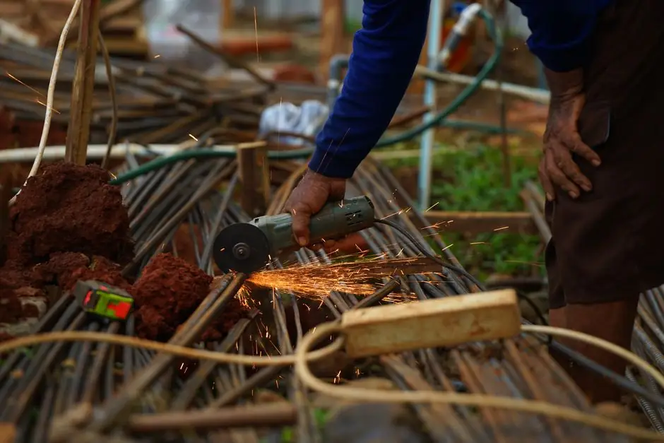
BS 8666:2020 is the British Standard that specifies how carbon-steel reinforcement is called up on a bar bending schedule, dimensioned, bent, and cut [S2][S3]. It replaces BS 4466 and applies to ribbed reinforcing bar to BS 4449 grades B500A, B500B, and B500C, plus ribbed stainless steel to BS 6744 [S1].
The standard lists 36 standard shape codes, 00 through 98, plus a generic code 99 that covers any geometry the standard catalogue cannot describe and must be accompanied by a fully dimensioned sketch [S1][S3]. Every standard code carries a fixed cut-length formula in the form L = A + (B) + ... minus bend-allowance terms, so a scheduler can convert a drawing into a mill cutting list without re-engineering each bar [S3][S5].
Former diameter and minimum bend radius table
Schedule 1 sets the binding geometry: for a general bend (including a closed link with bend angle at or above 150 degrees) the minimum former diameter M is 4d, and for an open link where the bend is below 150 degrees it rises to 8d, where d is the nominal bar size [S1][S2]. The corresponding minimum scheduling radius r is 2d (general) and 4d (link under 150 degrees) at the smaller end of the range, climbing with bar diameter up to 175 mm radius for 50 mm bar [S2].
For a 12 mm bar the table reads: r = 24 mm, M = 48 mm (general), and 96 mm for a tight link; the minimum end projection P is 125 mm for a general bend and 160 mm for a link below 150 degrees [S2]. Spring-back means the actual bar radius is slightly greater than half the former diameter, a tolerance worth remembering when verifying first-off bends on a rebar bender [S1][S2].
Reading a typical shape code formula
Shape code 13 is a 90-degree crank: L = A + 0.57B + (C) - 1.6d, with B at least 2(r + d) and the legs A and C each not less than P from the table [S1][S3]. Shape code 33 is the closed link: L = 2A + 1.7B + 2(C) - 4d, with A at least 12d + 30 mm and B at least 2(r + d) [S3][S5]. Shape code 51, the rectangular cape, is L = 2(A + B + (C)) - 2.5r - 5d, with C and D equal and capped by A and P [S2][S3].
Shape code 75 covers a single-pitch helix: L = pi(A - d) + B + 25, while code 77 is a multi-turn spiral L = C * pi(A - d) where C is the number of turns [S3]. Code 99 sits at the end of the catalogue and is mandatory whenever bend angles approach 90 degrees in non-standard geometry, when the critical dimension cannot be expressed as one of the fixed variables, or when five or more bends are present in a single bar [S1][S6].
Shape code selection by structural element

Standard shape mapping is largely conventional across UK reinforced-concrete practice. Straight bars or stock lengths use code 00 or 01. L-bars and U-bars in pile cages, ground beams, and base slabs typically use codes 21, 22, 24, 25, and 29. Closed links and stirrups in beams, columns, and walls draw on codes 33, 34, 35, 36, 41, 44, and 47. Helical and spiral confinement in columns and piles uses 75 and 77 [S3][S5].
Codes 31 and 32 cover a triangular link (3-bend closed), code 41 a 6-bend link, and code 56 a 6-bend diamond link used in coupling beams and diaphragm walls [S2][S3]. Code 48 is a 6-bend rectangular link, code 52 a 6-bend multiple-link, and codes 63 and 64 a 6-bend and 7-bend link respectively, both of which push against the "five or more bends" rule and frequently drift into code 99 with a sketch on real projects [S3][S5][S6].
Crank and acute-angle dimensioning rules
Extract 8.9 fixes crank geometry: the offset dimension must be at least 2d, and the angled length between bends is at least 10d for bars up to 16 mm and 13d for larger sizes [S1]. Extract 8.10 requires a minimum straight of 4d between the curved portions of any two bends in the same or opposite direction, with the gap x set to 10d (under 16 mm) or 13d (16 mm and above) [S1].
Acute angles are dimensioned along the tangent lines, not along the bar centreline, a frequent source of error when schedulers reuse older BS 4466 conventions [S1]. For shape code 12 (a single 180-degree return), the cut-length formula is L = A + (B) - 0.43R - 1.2d, where R is the internal bend radius, and both A and B must be at least (R + 6d) as well as not less than P [S1][S3].
Material, grade, and substitution limits
BS 8666 itself only governs scheduling and cutting; the material is fixed by BS 4449 (carbon steel B500A/B/C) and BS 6744 (stainless steel) [S1]. Schedule 1 of the standard notes that B500A in sizes below 8 mm does not conform to BS EN 1992-1-1, so a designer specifying A-grade in 6 mm or 8 mm must justify the substitution against Eurocode 2 ductility requirements [S1][S2].
Stainless steel to BS 6744 is called up on the schedule as a separate grade and type, with the same shape-code geometry, so fabricators running a rebar cutter and bender line can hold one geometry library across both material streams [S1]. Any reinforcement not in the B500 or BS 6744 families is scheduled as a special grade and type with material properties defined in the contract specification [S1].
Calculating cutting length in practice
Workflow on a real schedule starts with the shape code and the table-2 former diameter for the chosen bar size. The scheduler then reads the A, B, C, and (D) dimensions from the drawing, where bracketed values are the "free" or non-critical dimensions, and the schedule picks the minimum end projection P from the table when a leg is not dimensioned [S1][S5].
The cut-length formula is applied with the bar diameter d, the scheduling radius r, and where required the bend radius R, and the result feeds straight into a rebar straightener and cut-to-length line or a manual rebar cutter setup [S5][S7]. UK cutting-length calculators published in 2026 still apply the BS 8666:2020 formulae directly, including the pi(A - d) + B + 25 helix term and the 12d + 30 mm minimum A for code 33 links [S7].
When to break out of the standard catalogue
Code 99 plus a fully dimensioned sketch is the escape valve when geometry exceeds the catalogue: five or more bends, an acute angle below about 30 degrees, a critical dimension that the scheduler cannot express as a free variable, or a shape with two or more bends in different planes [S1][S6]. The sketch must carry A, B, C, and any additional letters with the same notation as the standard table, and the cut length is then calculated manually and approved before fabrication.
On the supply side, a rebar coupler detail, a starter-bar continuity strip, and any bar with welded plates typically ships as code 99 because the bend sequence interacts with the splice geometry, and the bend-allocation terms in the standard formula no longer apply. The sketch then drives the rebar bender setup sheet, including the former diameter from the table-2 selection. Procurement teams sourcing cut and bent reinforcement against BS 8666:2020 should expect fabricators to reject schedules that mix imperial bar sizes, that list B500A under 8 mm without Eurocode 2 justification, or that carry more than four bends without a code 99 sketch attached [S1][S3].
Trackable signals through the rest of 2026: BSI maintenance of BS 8666:2020 against the next BS 4449 amendment, and fabricator uptake of the code 75/77 helical formulae in automated rebar tool controllers, where cutting-length integration is now standard on newer CNC lines [S7]. Cross-reference procurement against the broader cement-equipment signal brief for downstream demand on cut-and-bent capacity.