
Draw wire transducers measure linear travel from a few hundred millimetres up to 50 m by converting wire retraction into shaft rotation, then into either an analog signal or an incremental encoder pulse train, with output format dictated by stroke, resolution, and PLC interface [S3][S4].
An analog draw wire sensor typically outputs 4-20 mA, 0-10 V, or a potentiometric (resistive) signal proportional to wire extension, while an incremental draw wire encoder outputs digital pulses on channels A, B, and Z, with common resolutions of 1024, 2048, 2500, 5000, and 10000 PPR per drum revolution [S4][S6].
Output Signal Categories and Physical Interface
Analog draw wire units almost always terminate in a current loop (4-20 mA) or voltage output (0-10 V), which can be wired directly to a PLC analog input module without quadrature decoding, and are commonly used on hydraulic cylinder position feedback, valve travel, and crane hoist positioning [S3][S4].
Incremental draw wire encoders expose discrete digital outputs through drivers such as NPN open-collector, PNP open-collector, push-pull HTL (8-30 VDC), TTL/RS422 (4.75-5.5 VDC, or 8-30 VDC variant), and line-driver (RS422 differential), with current draw at or below 60 mA per unit on typical Arduino-class interfaces [S1][S4].
Resolution, Linearity, and Effective Stroke
Analog draw wire transducers are limited by the resolution of the downstream ADC and by the linearity of the internal potentiometer or non-contact sensor, with practical effective resolutions in the 0.1-0.5 mm range over strokes of 1-10 m, while incremental units inherit the raw PPR of the rotary encoder, so a 2048 PPR encoder on a 200 mm drum circumference yields roughly 0.098 mm per pulse [S4].
Common incremental PPR values specified for draw wire units include 100, 360, 500, 1000, 1024, 2048, 2500, 4096, 5000, and 10000, and the index (Z) channel provides one pulse per revolution for homing reference [S1][S4][S6]. Quadrature decoding on A and B with x4 edge counting effectively multiplies the listed PPR by four, so a 2500 PPR device reads as 10000 counts per revolution [S6].
Power-Loss Behaviour and Position Retention
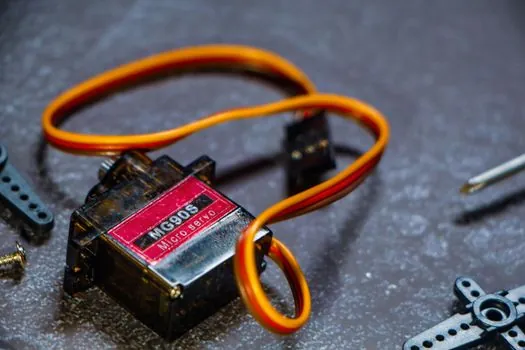
Incremental encoders lose absolute position on power cycle and must be rehomed against the index pulse or a known mechanical reference, whereas analog absolute draw wire units (and absolute SSI/CANopen variants) retain the last position on power restoration, which matters for vertical lifts, press slides, and any safety-rated axis [S3][S5].
For applications where a brief power interruption cannot be tolerated, the analog output with absolute encoding, or a serial absolute protocol such as SSI, is specified in place of an incremental HTL/TTL output, even though the incremental alternative is cheaper and faster to wire [S3][S5].
Electrical Noise, Cable Length, and Driver Choice
HTL (8-30 VDC) push-pull is more tolerant of long cable runs and industrial noise than 5 VDC TTL, while RS422 line driver outputs are preferred above 10 m of cable because the differential signalling rejects common-mode noise, and NPN/PNP open-collector outputs are generally limited to short cable lengths inside an enclosure [S1][S4].
For a 5 VDC Arduino or similar microcontroller input, TTL with a 4.75-5.5 VDC supply is the direct fit, and the 60 mA draw wire encoder current consumption sits well within the 5 V rail budget of a typical Arduino board, while HTL at 24 V requires a level shifter [S1].
Decision Matrix: Analog vs Incremental Encoder Output
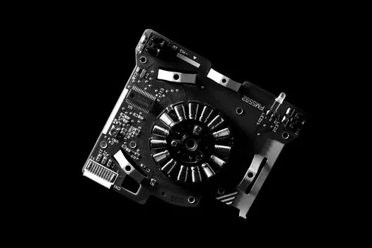
On cost, the analog (4-20 mA or potentiometric) draw wire transducer is the lower-cost option for short-stroke applications under 5 m and where only rough position is needed; incremental encoders cost more but deliver finer resolution for a given price point [S4][S5].
On integration effort, analog 4-20 mA needs only a single analogue input and scaling; incremental requires a fast counter or quadrature decoder, plus homing logic; on noise immunity, 4-20 mA current loop and RS422 line driver are the strongest; on absolute position retention, only analog absolute (or SSI absolute) units survive a power cycle without re-homing [S1][S3][S5][S6].
Typical Application Fit and Sourcing Notes
CNC machine tools, AGV lift masts, packaging cut-to-length, and elevator car positioning are the dominant draws for both families, and the encoder format inside the draw wire housing can be optical or magnetic, with magnetic offering better shock and vibration tolerance in mobile equipment [S4][S8].
For stroke lengths approaching 50 m, look for draw wire encoders that pair the long cable drum with a multiturn absolute encoder, since incremental pulse counts over very long wires become large integers that are awkward to manage without a 32-bit counter [S3][S4]. The decision typically reduces to: 4-20 mA absolute for simple retrofit on an existing analog PLC card; HTL incremental for high-speed, low-cost quadrature counting where homing is acceptable; RS422 incremental where cable runs exceed 10 m.
Component reference pages worth checking: draw wire sensor, linear encoder, and rotary encoder.
See also our earlier report, Waveguide in Magnetostrictive Level Transmitter: Process Contact vs. External Mounting.