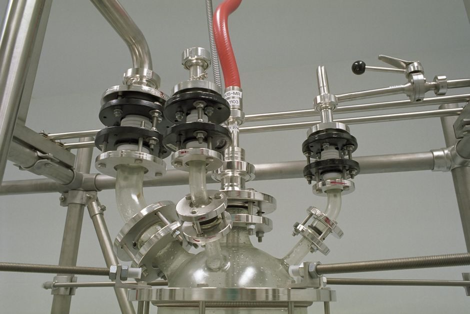
A flanged joint is thermally compatible with its piping only when calculated pipe-end displacement at design temperature stays inside the gasket's allowable seating shift and the bolt assembly's residual clamping load.
For a 10 m carbon-steel run (α ≈ 12.0 × 10⁻⁶ /°C) a 100 °C temperature rise produces roughly 12 mm of axial growth — a value that any Class 150 RF gasket will absorb, but that pushes a long-span straight run toward guided expansion anchors or a bellows-type expansion joint at every equipment connection.
Where the Compatibility Boundary Actually Sits
The compatibility boundary is set by three independent checks, not by the flange pressure class: pipe-end displacement versus gasket allowable shift, bolt thermal relaxation versus residual gasket stress, and anchor/guide reaction load versus the pipe-support structure. [S1]
ASME B16.5 flange classes (150 / 300 / 600 / 900 / 1500 / 2500) rate pressure–temperature capacity but do not by themselves address axial growth, lateral offset, or angular rotation between mating flanges; those movement limits live with the joint designer and the piping flexibility analysis (typically per ASME B31.3 or B31.1) [S2].
For a stainless water-conveyor case modeled in Inventor Nastran, a hydrostatic load combined with a temperature step drives a design where stiffeners and rubber supports share the displacement work — a pattern that maps directly to rubber-lined expansion joints on process lines [S2].
Selection Criteria: Flange Face, Gasket, Bolt, Joint Type
Specifying a thermally compatible joint requires four matched choices: flange facing (RF / FF / RTJ / tongue-and-groove), gasket style (spiral-wound, graphite, PTFE, RTJ metal ring), bolt material (B7 / B7M / B8 / B8M / B16), and movement-absorbing element (free pipe bend, expansion joint, expansion anchor, or guided support). [S2]
Key numerical thresholds: spiral-wound gaskets with graphite filler tolerate roughly -200 °C to +550 °C in oxidising service, while flexible graphite without metal reinforcement is limited to about +450 °C in air and requires a confined-ring geometry to retain bolt load during thermal cycling.
SS316 spiral-wound gaskets with inner and outer rings are the workhorse for Class 300 hydrocarbon duty at 200–425 °C; compressed non-asbestos gaskets are limited to roughly 260 °C peak and are the dominant failure point when a designer pairs them with steam service above their rating.
For RTJ (ring-type joint) flanges per ASME B16.20, the soft metal oval/ring is the seal — there is no gasket creep, but axial growth above ~3 mm will leak because the ring's seating travel is essentially zero after initial plastic set.
Comparison: Joint Movement Strategies on Four Decision Criteria
The main movement-handling options — natural pipe flexibility, metal bellows expansion joint, rubber expansion joint, and sliding / lateral expansion anchor — line up against four decision criteria as follows: axial movement capacity, lateral/angular capacity, pressure-temperature envelope, and maintenance access. [S2]
Natural pipe flexibility scores zero hardware cost and high reliability but fails on lateral capacity when the routing cannot absorb a long offset; metal bellows joints give roughly ±25 to ±100 mm axial stroke with multi-ply 304/316 stainless but cost more and require guide spacing set by the manufacturer.
Rubber joints with EPDM, NBR, or Viton liners handle axial compression of about 25–50 mm and lateral offset of 30–100 mm but cap at roughly 120–150 °C and 16–25 bar depending on the liner compound, and they degrade in hydrocarbon service unless the liner is FKM-rated.
Guided expansion anchors and pipe shoes convert thermal growth into controlled axial force on designated structures; they are the lowest-movement option but the highest-precision one, and they pair naturally with fixed-flange equipment nozzles where no bellows is allowed.
Who This Is For — and Who Should Walk Away
Thermal-expansion-aware flange design is for piping engineers running a flexibility analysis, EPC specifiers building a hot process train (steam, hot oil, refinery hydrocracker, ethylene, combined-cycle HRSG, district heating, solar thermal), and OEM skid builders mating a hot pump or compressor to cold piping. [S2]
It is NOT for cold-service utility water below 60 °C, ambient compressed air under 10 bar, or short (< 5 m) ambient-temperature copper or stainless domestic runs — the calculated ΔL falls inside the flange's seating shift and adding a bellows adds cost, leak paths, and a fatigue-limited part with no upside.
Real Failure Modes and Integration Pitfalls
The compatibility checks that pass on a datasheet and fail on site cluster around five patterns: bolt relaxation after thermal cycling, gasket creep under sustained high temperature, bellows convolute fatigue from cycle count, anchor over-reaction transferring thrust into a pump nozzle, and differential expansion between dissimilar flanges (e.g. stainless valve flanged to carbon-steel pipe, where α mismatch of roughly 4 × 10⁻⁶ /°C produces visible shear on the bolt studs). [S2]
Walk-down rule of thumb: any hot line (≥ 150 °C) longer than 30 m, or any line tied to rotating equipment with a fixed nozzle, gets a flange review against an actual expansion-mitigation device, not a "we'll let the pipe bend" assumption.
Cycle-count budgeting is mandatory for bellows: an AISI 316 multi-ply bellows rated for ±50 mm stroke at 1.6 MPa is typically life-rated for a few thousand full-stroke cycles, and halving the stroke roughly multiplies cycle life by an order of magnitude — the cheapest way to extend bellows life is to over-size the unit and run it at partial stroke.
Sourcing and Standards Anchors
Reference the design to ASME B31.3 (process) or B31.1 (power) for flexibility analysis, ASME B16.5 for flange dimensions and P-T ratings, ASME B16.20 for spiral-wound and ring-joint gaskets, and EN 13445 / EN 13480 for European pressure-equipment compliance.
Material selection for sour service follows NACE MR0175 / ISO 15156; bolting to ASTM A193 B7 / A194 2H for high-temperature, A320 L7 / A194 4 for low-temperature, and B8M / B8M for stainless — bolting grade is the most under-specified item in practice and the most common reason a hot joint loosens after the first heat-up.
Field-installed support hardware — expansion anchors, pipe shoes, and U-bolts — is typically sourced against MSS-SP-58 or equivalent, while the expansion joint itself ships under EJMA (Expansion Joint Manufacturers Association) calculations with the manufacturer's nameplate stamped axial, lateral, and angular ratings.
Trackable signals worth watching: an EJMA revision cycle currently underway, and ongoing discussion of spiral-wound gasket seating-stress limits under EN 1514-2 in the 2025–2026 review window [S2].
Related analysis: Shield Machine TCO: Cost Drivers, 10-Year Stack, and Spec Map.