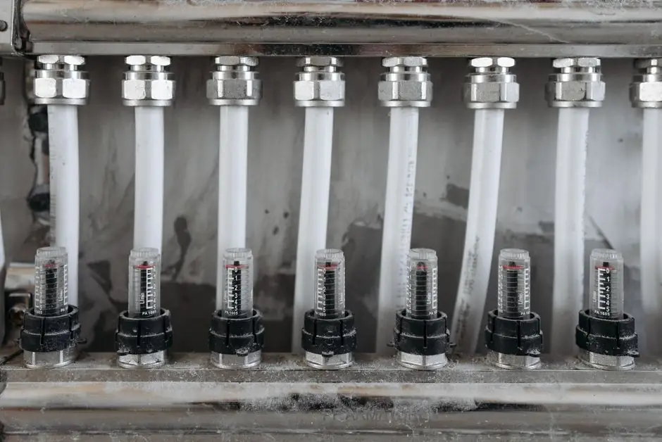
Selecting a flow sensor is a flow-range and velocity problem before it is a pipe-diameter problem. A 4-inch T-style impeller flow sensor typically starts accurate measurement at about 40 GPM, a 4-inch hydrometer-style unit at about 21 GPM, and a 4-inch iron ultrasonic unit below 1 GPM, with the HD-plastic ultrasonic variant at roughly 4 GPM [S3]. On a 10 m³/h service, shrinking the internal diameter from 100 mm to 50 mm lifts the average velocity from approximately 0.35 m/s to about 1.41 m/s, a roughly four-fold jump from the same flow [S5].
These two facts, minimum measurable flow and the squared effect of diameter on velocity, drive almost every decision in this guide. The job is to pin the operating envelope first, then pick a technology whose measurement window fits it, then verify pressure, temperature, medium compatibility, and installation geometry [S1][S5].
Build the operating envelope before you pick a body size
Engineers should first tabulate a flow envelope covering six conditions: shutdown or drain state, normal startup, normal operating range, extreme steady-state operating range, normal shutdown, and any credible abnormal condition [S1]. The flow envelope, not the line-size tag, decides which sensor technology can read the low end and survive the high end. A flowmeter that performs well only at one operating point is a service failure waiting to happen when the process swings.
A second axis to record at the same time is the required turndown, often expressed as the ratio of maximum to minimum flow the meter must read within spec. ISA guidance flags that some flowmeters are much better at low-flow turndown than others, and the accuracy guarantee must be checked against the expected range, not against a single best-case number [S1]. On irrigation-class meters, the practical consequence is concrete: 2-inch sensors with a 10 GPM minimum floor cannot see MP Rotator, tree, or bubbler stations, so the operator has to disable flow monitoring on those zones [S3].
Accuracy, repeatability, and rangeability are three different numbers
Accuracy is how close the reading is to truth; repeatability is how close consecutive readings are to each other; rangeability is how much of that accuracy and repeatability the meter holds across its full flow range [S1]. The archer analogy used in ISA's automation-basics material is sharp: a tight cluster off the bullseye is repeatable but not accurate, and a meter with no accuracy statement on the datasheet, only a repeatability figure, deserves scrutiny [S1].
The hard engineering consequence is selection logic. A meter with good repeatability and poor accuracy can be re-zeroed; a meter with poor repeatability cannot be salvaged because there is no consistent signal to trim [S1]. When a vendor quotes accuracy, the spec sheet should be read at the minimum, normal, and maximum points of the envelope, not just at the sweet spot, because rangeability failures usually show up at the low and high tails of the curve [S1][S5].
Velocity window, not diameter, decides the right body
For circular pipe, the governing relation is Q = v × A, and v = 4Q / πD², which means internal diameter has a squared effect on velocity [S5]. The practical rule many spec sheets enforce is a target velocity window of roughly 1–3 m/s for clean water in many inline technologies, with the exact window set by the meter family. Below the floor, the signal-to-noise ratio collapses; above the ceiling, erosion, cavitation, and pressure loss become real.
Because of the squared term, undersizing the meter body is one of the most common ways to push a borderline application out of its velocity window. Halving the internal diameter on a fixed flow multiplies velocity by roughly four, so a meter that looked comfortable in the line-size tag can be instantly over-ranged once installed [S5]. Insertion probes, clamp-on ultrasonic, and reduced-bore configurations exist precisely to retune the velocity into the meter's usable band without cutting the line.
Match the technology to the medium and the duty
Five meter families dominate the selection matrix, and each maps to a different duty [S2][S3][S4]:
1. Electromagnetic (mag) meters: no moving parts, require conductive liquid, immune to most suspended solids; common in water, wastewater, and slurry service [S4].<br/>2. Vortex meters: shed-frequency principle, good for steam, gas, and clean liquids; published selection software maps process conditions to body size and model code [S4].<br/>3. Ultrasonic (inline and clamp-on): no pressure loss, no moving parts, the high-resolution option for clean and treated water, with iron-body variants reaching sub-1 GPM low-end detection on 4-inch lines [S3].<br/>4. Coriolis: direct mass measurement, best for two-phase or custody-transfer liquids, the accuracy benchmark but the highest cost per line.<br/>5. Turbine, nutating-disc, and compound (mechanical) meters: legacy workhorses with moving parts; common in municipal water and irrigation retrofits, with the well-known minimum-flow floor [S3][S4].
Process conditions frequently decide before diameter does. Conductivity, viscosity, gas entrainment, temperature, pressure rating, lining compatibility, and clean-pipe requirements each rule out one or more families outright [S5]. Sizing software published by vortex, mag, and Coriolis vendors then runs the surviving candidates against the flow envelope to recommend a body code [S4].
Installation geometry, straight-pipe, and full-pipe requirements

A correct-size meter installed in a disturbed flow profile will read wrong on day one. Upstream disturbances from valves, pumps, reducers, and tees create swirl and asymmetric velocity profiles that bias most technologies, especially vortex and turbine, while electromagnetic meters tolerate more profile distortion but still want a calibrated profile [S5]. Clamp-on ultrasonic is the most forgiving on retrofits because the transducers sit on the outside of the existing pipe, but it needs accurate pipe material, wall thickness, and lining data to set the sound-path calculation [S5].
Full-pipe conditions are non-negotiable for most inline designs. A partially filled line drives the velocity calculation off the true cross-section and biases every reading; in horizontal drain lines, that usually means installing the meter in a raised section or a U-trap to guarantee a flooded measurement section [S5]. Output-signal compatibility (HART, Foundation Fieldbus, PROFIBUS PA, pulse, 4–20 mA) and acceptable pressure loss should be checked against the existing control system, since a meter that is hydraulically perfect but speaks the wrong protocol is a stranded asset.
Who should NOT pick a same-size-as-line meter
Same-size selection is a trap in three common cases. First, very low flow rates relative to line capacity: a DN100 chemical-injection line that only sees 1–3 m³/h is far below the velocity window of most DN100 meters, so a reduced-bore or insertion probe is the right call [S5]. Second, steam and high-temperature gas services where published vortex sizing tools recommend a specific reduced-bore body to keep the shedder in its Reynolds window [S4]. Third, retrofit irrigation and water-distribution upgrades where the existing mechanical meter is over-sized for the new low-flow zones; ultrasonic or hydrometer-style units deliver the lower minimum flow that modern zone valves actually demand [S3].
Choosing the body to match the meter, backflow preventer, or master valve is a widespread error in the irrigation channel and it produces the same operational failure mode: a sensor that cannot see the lowest operating point of the system, so monitoring gets disabled and the safety and leak-detection benefits are lost on the very stations that need them most [S3].
Shortlist logic and the next decision node
The shortest reliable shortlist runs in this order: (1) build the flow envelope and the velocity window; (2) filter technologies by medium, conductivity, temperature, and pressure; (3) run the surviving candidates through vendor sizing software to get a recommended body code [S4]; (4) verify straight-pipe, full-pipe, and signal-protocol fit; (5) confirm accuracy and repeatability specs at the low and high ends of the envelope, not just the mid-point [S1]. The next trackable signal after that is the calibration certificate: a meter shipped with a traceable flow calibration on a rig that covers the operating range, with the cal data filed against the asset tag, is the audit-ready outcome this workflow is meant to produce. For comparison on the parallel problem in motion-control sizing, the stepper motor sizing workflow applies the same envelope-first logic to torque and inertia.