Selecting a stepper motor for a given load torque and speed is a curve-matching exercise, not a catalog sweep: the required operating point must sit below the motor-driver torque-speed curve with a 30-50% margin, and the reflected load inertia must stay within a workable ratio of the rotor inertia [S2][S5].
Stepper motors are open-loop positioning devices that convert input pulses into discrete mechanical steps, with rotor speed proportional to pulse frequency and shaft angle proportional to pulse count; most standard hybrid steppers hold ±0.05° (about ±3 arc minutes) per step with non-accumulating error, which is why they dominate low-cost positioning tasks but stall without feedback if torque is misjudged [S4][S1].
Define the Motion Profile Before Touching a Catalog
Build the worst-case move profile first: move distance per cycle, cycle time, positioning accuracy, load mass and geometry, and the transmission (leadscrew lead, pulley radius, or gearbox ratio) that couples load inertia back to the motor shaft [S5][S2].
The required torque at the motor shaft is the sum of friction torque (T_f) plus acceleration torque (T_α), where T_α = (J_motor + J_ref) × α and α is the angular acceleration in rad/s²; for a leadscrew, J_ref = m·p² / (4π²), and for a belt-pulley, J_ref = m·r², with m the linear load mass, p the screw lead in meters per revolution, and r the pulley radius [S5].
Frame size is a mounting hint, not a torque guarantee: two NEMA 23 motors can differ by 50% in torque output, and NEMA 17/23/34 designations only fix the bolt pattern, so the torque-speed curve is the document that actually decides the build [S5].
Match the Operating Point to the Torque-Speed Curve
Pull-out (or pull-out) torque is measured by ramping a motor to a target speed with no load, then adding rotary load until synchronism is lost; the curve traces the maximum sustainable load across the speed range and is the single most important graph on the datasheet [S3][S6].
Published torque-speed curves are valid only for a given motor AND a given driver at a given supply voltage, because holding and dynamic torque both depend on the drive's chopper current and bus voltage; swapping drivers moves the curve, so the curve must be requested for the exact drive the system will use [S4][S1].
A practical rule is to size at the highest torque × speed operating point and add at least a 30% safety margin on top of the required torque and speed; this buffer covers peak loads, voltage sag, and unmodeled friction, and is the difference between a motor that runs in the lab and one that survives three shifts on the line [S2].
Verify Inertia Ratio and Resonance Headroom

For larger steppers, the reflected load inertia should sit in a workable range relative to the rotor inertia, because a high ratio hollows out acceleration torque at higher speeds while a too-low ratio amplifies mid-band resonance; the Faulhaber workflow explicitly adds inertia as a load parameter once the motor is large enough that acceleration dynamics matter [S2][S5].
Resonance is the structural limit most catalogs hide: variable-reluctance, permanent-magnet, and hybrid designs all exhibit mid-speed resonance bands where the rotor's electrical and mechanical time constants interact, and a properly tuned microstepping driver plus a compliant coupling is what gets a system through that band without losing steps [S1][S4].
If a stepper will be operated near or above 3000 rpm, plan on a different architecture: standard steppers are not easy to run at very high speeds, and switching to a closed-loop stepper (with an encoder) or a true servomotor becomes the more reliable choice [S1][S3].
Stepper Family Comparison on the Decision Criteria That Matter
Three stepper families cover almost every industrial build, and they line up against cost, step resolution, available torque, and speed ceiling as follows [S1][S3][S4]:
Variable-reluctance (VR): toothed soft-iron rotor, wound stator, no magnet, low cost, but lower torque density and rougher step quality, so it is now rare in new industrial designs.
Permanent-magnet (PM, "tin can" / can stack): 2-phase, 7.5°-15° step angle (24-48 steps per revolution), moderate torque, lowest cost, common in printers and small valves; Portescap's can stack and disc magnet product lines sit in this family [S3][S1].
Hybrid: combines PM and VR principles, the standard 1.8° step (200 steps/rev) with ±0.05° accuracy, the highest torque density, and the broadest industrial following, including the entire NEMA 17/23/34 frame set [S4][S1].
Adding an encoder closes the loop and lets the same motor run with full torque at higher speeds and at zero lost-step risk, at the cost of the encoder, a more advanced drive, and the wiring it requires [S3].
Driver, Microstepping, and Supply Voltage Choices
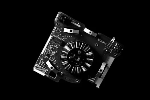
A stepper system is four coupled parts: a controller or PLC, an indexer that issues step/dir pulses, a driver that chops current into the windings, and a power supply; changing the supply voltage changes the high-speed portion of the torque curve, because back-EMF limits how fast current can be forced into the windings [S4].
Microstepping trades continuous torque for resolution and smoothness: half-step mode delivers about 15% less torque than full-step on the same motor, and sine-wave current control (typical of a quality chopper drive) is what lets the motor reach its rated low-speed torque without cogging [S7].
On the sizing math, the practical safety factor on total required torque is 1.5 to 2.0× to absorb unmodeled friction, supply sag, and temperature; on the inertia side, sizing tools (Kollmorgen's Stepper Optimizer is a common example) compute the load profile against the candidate curve in seconds and are a faster first pass than hand calculation on every iteration [S5][S8].
Where Open-Loop Steppers Win, and Where They Lose
Open-loop steppers fit short, quick, repeated moves: low rotor inertia gets them up to speed fast, full holding torque at standstill (with windings energized) keeps the load put, and the digital pulse interface lets a PLC or indexer drive them with no encoder, no tuning, and no feedback cable [S4][S1].
They lose on three jobs: high-speed continuous rotation (back-EMF and resonance erode torque above a few thousand rpm), applications with widely varying loads (a single missed step in open loop is a silent positioning error), and tasks that demand servo-grade dynamics, where a closed-loop stepper or a brushless servo is the right tool [S1][S3].
For motion control architectures that pair the stepper with a variable-speed drive front end or a dedicated stepper drive, the stepper drive selection is inseparable from motor sizing, and the broader stepper motor family page covers the technology trade-offs behind each topology.
Selection Workflow and Verifiable Next Signals
The condensed workflow: (1) draw the worst-case move profile; (2) compute T_f and T_α and reflect load inertia to the motor shaft; (3) apply a 1.5-2.0× safety factor; (4) overlay the operating point on candidate torque-speed curves taken with the actual driver and supply; (5) check inertia ratio and resonance band; (6) only then pick the frame and order the drive [S5][S2][S4].
Trackable signals after the selection: actual stage temperature after a 30-minute dwell at peak current (should stay within the motor's insulation class rating, typically 130°C for class B), and measured pull-out torque at the application's top speed using a torque sensor or a torque wrench tester in line with the load; both numbers are easier to verify than to predict.
This topic is covered further in Counter-Drone Procurement Wave: A Buyer's Map of the Late-2026 IDIQ Landscape.