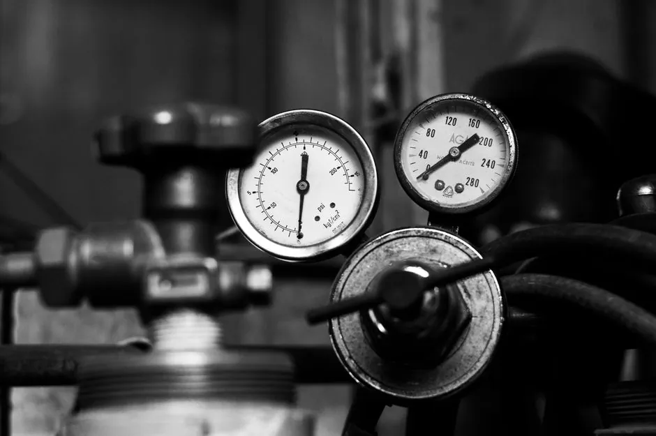
An FRL (filter, regulator, lubricator) installation on a 1/2" NPT train is rated for 150 PSIG (10.3 bar) maximum air pressure, 106 SCFM (3,000 LPM) maximum flow, and 150 deg F (65 deg C) maximum air temperature per manufacturer specification data [S3]. Installers must close the air line system by turning off the air pressure in the work area before any fitting work begins, then mount the unit so the airflow arrows on the housing point in the direction of system flow; reversed orientation can damage internal components [S3].
Proper FRL installation pays back through three measurable channels: reduced pressure-related power waste, fewer downstream valve and cylinder replacements, and lower contamination-driven downtime [S1][S2]. A correctly installed FRL train is also the prerequisite for compliance with ISO 4414, the general rules and safety requirements for pneumatic systems and their components referenced in OEM installation manuals [S3]. For spec context, an FRL unit combines a 5 micron particulate filter, a spring-loaded diaphragm regulator, and an oil-mist lubricator into a single manifold or modular assembly.
Site selection: free of sunlight, chemicals, and heat
Selecting the installation site as close to the actual work area as possible minimizes pressure drop between the FRL and the point of use, which directly protects downstream valve and cylinder service life [S3]. The site must be free of direct sunlight, excessively high temperatures, and hazardous chemicals, since bowl-mounted polycarbonate reservoirs degrade under UV and soften above 150 deg F (65 deg C) [S3]. Clean, dry, and cool locations away from direct sunlight, with easy access for maintenance, are the standard engineer-level siting criteria [S2].
Hot or dusty environments accelerate filter element loading and lubricant oxidation; placement in a clean, controlled area extends service intervals and stabilizes regulator setpoint drift [S2]. If the FRL serves a single machine tool or actuator, mount it within 3-5 pipe diameters of the device; if it serves a header feeding multiple drops, mount it on the header itself with secondary point-of-use regulators on each branch. Plant air that exceeds 100 deg F (38 deg C) at the FRL inlet will shorten lubricant life and push bowl-thermo limits, so add a refrigerated or desiccant air dryer upstream when header temperatures run high.
Mounting, orientation, and NPT torque discipline
Mount the FRL unit, or its individual filter, regulator, and lubricator modules, in the air line with the arrows on the unit pointed in the direction of airflow within the system; failure to orient the arrow correctly can damage the diaphragm and valve assembly [S3]. Use sturdy brackets or mounts, and verify the assembly is level and stable so that the lubricator sight dome reads accurately and the filter auto-drain (where fitted) functions on a vertical plane [S2]. Most modular FRLs ship with a mounting bracket kit and accept a standard 1/2" NPT thread; the included 3/8" reducer bushings must not be over-tightened, since they will not fully engage after torque-up and the manufacturer provides a dedicated tightening torque chart on page 6 of the manual [S3].
A common 10690-class FRL train weighs 2-4 lb (roughly 1-2 kg) empty, so a single M5 or 1/4-20 bracket screw per module is normally sufficient on a flat panel. Always apply PTFE tape or anaerobic thread sealant to male NPT threads; do not use liquid pipe dope on polycarbonate bowls, where drips can craze the plastic. Where vibration is present (compressors, stamping presses), add a rubber isolating mount and a flexible hose section upstream of the FRL to prevent regulator setpoint creep.
Air supply connection and leak-down check
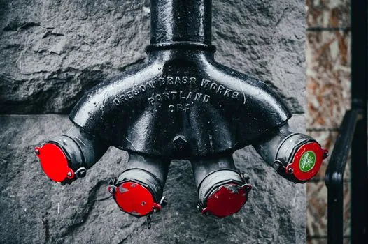
Step 3 in the install sequence is connecting the compressed air supply line to the FRL inlet, using proper fittings and sealants to prevent leaks [S2]. Once the inlet is made and the outlet run to the downstream equipment is attached with appropriate fittings and hoses, open the air line system and check for leaks around the FRL unit before energizing any tooling [S2][S3]. A soap-and-water or ultrasonic leak check at 100 PSIG will reveal thread-seat leaks that a visual inspection misses; a 5-minute hold at working pressure with the regulator set mid-range and downstream isolated is a good commissioning rule.
Sizing matters as much as sealing: undersized FRL units create excessive pressure drop that starves cylinders and overworks the compressor, while oversized units cost money and add dead air volume that slows regulator response [S2]. A standard rule of thumb is to size the FRL flow rating at 1.5-2x the actual SCFM demand of the downstream circuit; this keeps pressure drop across the FRL below 5 PSIG at full demand. For comparison, the spec sheet 10690-class unit at 106 SCFM (3,000 LPM) handles most single-tool drop installations, while a 1" NPT header FRL at 250+ SCFM is needed for plant-loop service.
Regulator adjustment and dual-gauge verification
Regulator adjustment must be performed while verifying the displayed values of the inlet and outlet pressure gauges; turning the knob excessively can cause damage to the internal diaphragm and valve spring, and the pressure regulator knob should be adjusted by hand only, with no tools [S3]. Set the desired air pressure using the regulator, referring to equipment specifications for optimal pressure settings rather than dialing by feel [S2]. A typical dual-gauge FRL block shows inlet (supply) pressure on one face and outlet (regulated) pressure on the other, so the installer can confirm both the upstream header condition and the downstream setpoint simultaneously.
Set the regulator with the downstream machine isolated or its valve in the closed position, then bring the load on slowly; this prevents pressure overshoot from charging an empty downstream volume. If a downstream device requires 80 PSIG but the compressor idles at 110 PSIG, the regulator must hold setpoint within roughly 5 PSIG as the compressor cycles, which is well inside the capability of any spring-loaded diaphragm regulator on the 10690-class platform. Always back the adjustment knob fully counterclockwise (to lowest pressure) before re-pressurizing, then rotate up to the target setpoint, to avoid spring pre-load damage from a slam-set.
Lubricator fill and oil-mist calibration
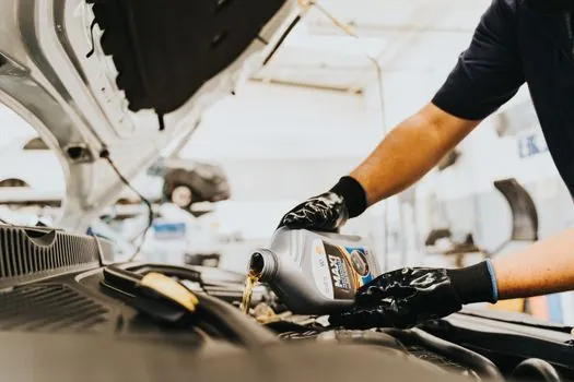
Fill the lubricator oil bowl with air tool oil of the viscosity and additive package recommended by the OEM (typically ISO VG 32 with rust and oxidation inhibitors); automatic drip-rate lubricators are typically set to 1-2 drops per minute per 10 SCFM of flow, but the exact rate must be verified against the sight dome on the unit [S3]. Modern self-lubricating seals in most pneumatic tools and cylinders remove the need for a lubricator entirely, so confirm whether the downstream equipment is rated for oil-mist or oil-free service before adding the L-module [S1].
For non-lubricated systems, omit the lubricator and use a filter-regulator (FR) pair instead of a full FRL, since stray oil can foul solenoid seals, contaminate paint lines, and attack food-grade or pharmaceutical piping. Refill intervals on the oil bowl depend on flow and drip setting; a 6 oz (180 mL) bowl on a 20 SCFM circuit with a 1 drop/minute setting typically needs refilling every 40-60 operating hours, but a sight-glass check is the only reliable trigger. For further spec context on how a regulator's diaphragm response interacts with downstream motion-control hardware, see the linear guide selection reference.
Common install mistakes and when to replace rather than repair
Three pitfalls dominate failed FRL installations: neglecting maintenance (filter replacement and lubricator refilling), improper sizing (undersized or oversized units causing pressure drop or sluggish response), and incorrect placement in hot or dusty environments [S2]. Reversed airflow orientation, the most common mechanical install error, can crack the regulator diaphragm on the first pressurization cycle, so always recheck the arrow against the system flow direction before opening the upstream ball valve [S3]. A cracked bowl, a non-sealing auto-drain, or a regulator that will not hold setpoint within roughly 10% of dialed pressure is a replacement item, not a field-repair item; do not attempt to bond a polycarbonate bowl with solvent cement, as the joint will fail under pressure.
Document the regulator setpoint, the filter element part number (5 micron on the 10645 element used in the 10690-class unit), and the lubricator oil grade on a permanent label fixed to the FRL bracket, so the next maintenance technician restores the original calibration rather than guessing [S3]. Build a 30-60-90 day inspection cycle into the plant CMMS: drain the filter bowl weekly, replace the filter element quarterly (sooner if pressure drop exceeds 5 PSIG across the element), and rebuild the regulator every 2-3 years or on any sign of setpoint creep. The relevant plant-flow planning context for spec engineers comparing FRL trains to broader instrument and compressor room layouts is covered in the measuring instruments demand 2026-2030 forecast, which frames where pneumatic conditioning hardware fits inside the wider industrial-instrument spend pool.