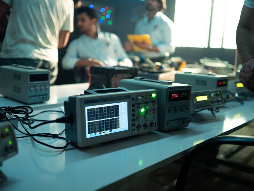
A function generator is a stimulus instrument that synthesises sine, square, triangle, ramp, pulse and arbitrary waveforms over a defined bandwidth, sample rate and amplitude window; selecting one is fundamentally about matching five numeric axes — frequency range, sampling rate, vertical resolution, channel count, and modulation depth — to the load under test [S1][S2].
The category spans three practical tiers: analog/DDS bench units to roughly 25-50 MHz, mid-range true-arbitrary generators from 100 MSa/s to 1 GSa/s, and high-end AWGs (Arbitrary Waveform Generators) above 1 GSa/s with 14-16 bit vertical resolution. Buyers routinely confuse DDS (Direct Digital Synthesis) with arbitrary — DDS sweeps standard shapes by phase accumulation and excels at agile frequency hopping, while true-arbitrary stores a finite point record in memory and clocked-out at a fixed sample rate, which sets its useful bandwidth [S2].
Bandwidth and Sample-Rate: The First Hard Gate
Useful sine output on any function/arbitrary generator is normally rated to roughly 40-50% of the maximum sample rate (Nyquist-limited for arbitrary, less restrictive for DDS continuous modes), so a 250 MSa/s box puts a clean sine ceiling near 100 MHz before amplitude rolls off and harmonic distortion climbs [S2].
Square and pulse waveforms stress slew rate rather than sample rate: edge times below 5 ns demand an analog front-end rated for that rise, regardless of the DAC (Digital-to-Analogue Converter) behind it. A unit advertising "100 MHz" on sine but quoting 8 ns edge on pulse is normal — square-wave fidelity and sine bandwidth are two different specification lines and must be checked separately [S2].
For modulated carrier work (AM/FM/PM/FSK/PSK), the modulator bandwidth sits inside the carrier envelope: a generator with 30 MHz carrier and 5 MHz internal modulation source is adequate for comms receiver stimulus, while radar IF (Intermediate Frequency) replication typically needs 100+ MHz modulator bandwidth and ≥1 GSa/s arbitrary memory to hold a real pulse-compression record without aliasing [S2].
Vertical Resolution: 8, 10, 12, 14 or 16 Bit
Vertical resolution sets dynamic range: each extra bit adds roughly 6 dB of SFDR (Spurious-Free Dynamic Range). An 8-bit generator sits near 48 dB SFDR and is acceptable only for digital logic stimulus; 10-bit (~62 dB) covers most general bench use; 12-bit (~74 dB) is the practical floor for audio and low-frequency analogue work; 14-16 bit units target communications and radar baseband where harmonic spurs must stay below -70 dBc. [S1]
For a buyer comparing two boxes at the same sample rate, the higher bit count usually wins for waveform fidelity, but memory depth also matters: a 14-bit generator with only 8 k points cannot replay a long radar pulse without an internal loop that repeats the same record, which creates periodic artefacts. Rule of thumb: arbitrary memory of ≥1 MSa (MegaSamples) per channel is the minimum for general stimulus; ≥16 MSa per channel is the comfortable working point for communications and ultrasonic test [S2].
Channels, Coupling and Synchronisation
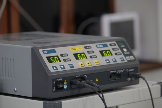
Single-channel generators are sufficient for amplifier frequency-response sweeps, filter characterisation and clock substitution. Two channels become mandatory for I/Q modulation, three-phase motor drive emulation, differential signalling (RS-485, LVDS) and audio two-tone intermodulation testing, where a separate channel holds the second tone or the quadrature baseband [S2].
Channel-to-channel skew on dual units is typically specified at <1 ns; lower is rarely needed outside high-speed serial protocol work. Coupling between channels can be independent, summed, or phase-locked — the latter is essential when synthesising three-phase PWM (Pulse Width Modulation) drives, where the third waveform is derived internally rather than from a second physical DAC. Buyers should confirm whether dual-channel outputs track each other in frequency with zero offset (good for balanced signalling) or operate as fully independent arbitraries (needed for two-tone IMD (Intermodulation Distortion) testing) [S2].
For bench integration, drivers matter as much as raw spec: the IVI-C (Interchangeable Virtual Instruments – C) class used by MATLAB's Quick-Control `fgen` interface allows the same MATLAB script to address any compliant generator via a `fgen('TCPIP0::172.31.57.100::inst0::INSTR')` resource string or a named driver such as `Agilent332x0_SCPI` over GPIB (General Purpose Interface Bus) [S2]. That abstraction lets a test station swap bench generators without rewriting test code, which is a real procurement argument when standardising across labs.
Modulation, Sweep and Burst: Built-in Versus Arbitrary
Most mid-range generators ship with built-in AM, FM, PM, FSK, PSK and ASK modulators whose depth and deviation are settable in % or Hz. Maximum FM deviation is typically limited (e.g. ±100 kHz on a 25 MHz carrier); beyond that, the deviation must be embedded into an arbitrary waveform and replayed at the matching sample rate, which is the only realistic path for wide-deviation chirp or complex digital modulation replay [S2].
Burst mode has two distinct flavours: gated burst (output runs while a gate signal is high) and triggered burst (N cycles per trigger event). The number of cycles per trigger is settable, and the internal trigger rate is configured in triggers-per-second, allowing paced simulation of repetitive transients without an external pulse generator [S2].
Sweep mode covers linear and logarithmic frequency sweeps, with start/stop frequencies and dwell or step time configured per the manufacturer's SCPI (Standard Commands for Programmable Instruments) dictionary. Buyers targeting filter characterisation should verify that the generator's sweep output is accompanied by a synchronised X-axis drive signal (ramp or Z-blank) so an oscilloscope can plot Bode magnitude without manual timing alignment.
Who Needs What: Use-Case Shortlist

For student labs, hobby electronics and TTL/CMOS (Transistor-Transistor Logic / Complementary Metal-Oxide-Semiconductor) logic verification, a 10-25 MHz DDS unit with 1 channel and 8-10 bit vertical resolution is sufficient; total cost of ownership stays low and the learning curve is short. Audio and low-frequency analogue work, including amplifier THD+N (Total Harmonic Distortion plus Noise) sweeps and filter alignment, calls for 12-bit vertical resolution and sine bandwidth to at least 1 MHz; arbitrary memory of 1 MSa is enough. [S1]
Communications receiver and module test needs 50-100 MHz carrier with internal AM/FM modulation sources, 2 channels for I/Q, and SCPI/IVI-C driver support so ATE (Automatic Test Equipment) frameworks such as MATLAB can address the box without custom code [S2]. Embedded bus and serial protocol compliance testing (CAN, LIN, RS-485, SPI, I²C) is dominated by edge quality — sub-5 ns rise/fall and low jitter — not by carrier bandwidth, so a generator with a fast pulse channel and adjustable amplitude to 5 V into 50 Ω is the priority.
Who should NOT pick a low-end DDS-only bench unit: anyone testing radar IF stages, OFDM (Orthogonal Frequency-Division Multiplexing) baseband, or ultrasound pulser response, because the sample rate and bit count simply will not hold waveform shape. Those buyers should move directly to a true-arbitrary 500 MSa/s or higher unit with ≥14 bit vertical resolution and ≥16 MSa memory, accepting the price jump because there is no spec-compliant middle ground.
Failure Modes, Limitations and Procurement Pitfalls
Common selection mistakes include: trusting the headline "sine frequency" without checking the amplitude-flatness spec (most units are derated to 0.5 dB or 1 dB at maximum frequency, not at full amplitude); ignoring output impedance — most generators default to 50 Ω but can be set to high-impedance mode, and the displayed amplitude only matches the load when the matching is correct; and treating "arbitrary waveform memory" as equivalent to "sample rate" — a long memory at low sample rate cannot raise the analogue bandwidth. [S2]
Connection and driver compatibility is another real pitfall: the MATLAB `fgen` interface documented in [S2] only works with instruments backed by an IVI-C driver; legacy SCPI-only boxes require either vendor-supplied MATLAB drivers or a custom VISA (Virtual Instrument Software Architecture) wrapper. Specifying a generator without confirming IVI-C or VISA plug-and-play support on the procurement sheet routinely delays ATE integration by weeks.
Finally, isolation, ground loops and safety: bench generators with floating outputs (the BNC outer shell isolated from earth) are needed when stimulating a circuit that is itself earth-referenced at a different potential, such as a motor-drive low-side current shunt or a battery management BMS (Battery Management System). Buying a non-floating unit to save cost usually forces the test bench to use an isolating transformer, which negates the saving.
Selection logic in one line: define the highest carrier frequency needed, set the sample-rate floor at ≥2.5× that figure for sine or ≥10× for arbitrary pulse, fix the bit count at 10 for digital/12 for analogue/14 for RF (Radio Frequency), choose 2 channels if I/Q or three-phase is on the roadmap, and require IVI-C plus a synchronised sweep output if the box will live inside an automated test rack rather than a manual bench — units meeting all five gates are the realistic shortlist for any 2026 procurement [S2]. For broader process-control context where a function generator sits beside a pressure transmitter on a calibration bench, the same five-axis logic applies: bandwidth, sample resolution, channel count, modulation envelope, and driver interface determine fit.
For component-level specifications, see function generator, and vacuum generator.
This topic is covered further in How to Choose a V-Ribbed Belt: Spec-Driven Selection for Engine and Accessory Drives.