A signal calibrator is an active source/sink that generates or measures DC voltage, DC current, and resistance; the HIOKI U8794, for example, outputs DC voltage from -0.1000 V to +5.3000 V at 0.1 mV resolution and DC current across four ranges down to a 50 µA range with 0.001 µA resolution [S1].
Test leads, in contrast, are passive wire assemblies terminated with banana plugs, probes, or alligator clips whose job is purely to carry the signal between the device under test, the calibrator, and the multimeter — they neither source nor measure [S4]. The distinction decides which item shows up on a loop-commissioning bill of materials.
Core Function Split: Active Source/Sink vs Passive Conductor
A signal calibrator replaces a real sensor on the bench: it forces a known voltage, current, or simulated resistance into the loop so the receiving PLC, indicator, or recorder can be verified end-to-end. The U8794 is explicitly an ECU-inspection simulation source, with 8 isolated channels on a 25-pin D-sub connector, each channel isolated from the chassis at a max rated voltage to earth of 25 V [S1]. That isolation is the reason bench engineers reach for a multi-channel calibrator instead of tying four bench supplies together.
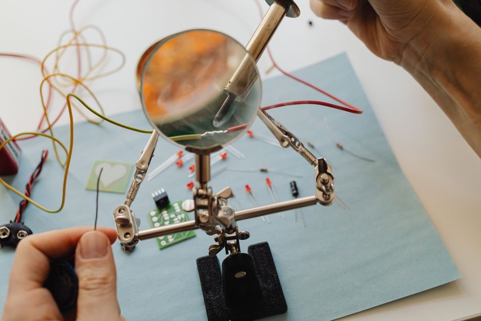
Test leads carry the calibrator's output to the terminals. Hook-up wire, banana-plug leads, and multimeter probe kits sold by dedicated manufacturers are typically built from tinned copper conductors with silicone or PVC insulation, and the only electrical specifications that matter are conductor resistance, current rating, and the safety category (CAT II / CAT III / CAT IV) of the plug and probe stack [S4]. Specifying a 10 A lead on a 4-20 mA loop is electrical overkill, but specifying a CAT II lead on a 480 V motor control center is a safety failure — the leads are governed by insulation and category, not by signal accuracy.
Decision Criteria: When You Need a Calibrator, When You Only Need Leads
The decision tree is short. If the work involves verifying a transmitter's output, trimming a loop calibrator range, or simulating a load cell, the calibrator is the tool that does the work; leads are the wiring that gets the signal to the DMM. The CALOG-LC, for instance, is built specifically to test 4-wire and 6-wire load cells, check insulation breakdown, and simulate mV/V output — none of those tasks can be done with passive leads alone, because the device must both source excitation and read microvolt-level return signals [S2].
Leads become the primary tool only when the engineer is tracing an existing loop, checking continuity, or measuring with a handheld multimeter. For those tasks, a pressure calibrator is overkill; the relevant specs are conductor cross-section (typically 20-18 AWG for general bench work), insulation voltage rating, and the safety category of the probe tip. A pair of CAT III 1000 V silicone leads with shrouded banana plugs covers most plant troubleshooting without any active source at all [S4].
Comparison Matrix: Calibrator vs Test Leads Across Six Spec Gates
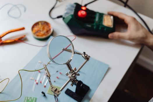
Cost per channel: a multi-channel signal calibrator like the U8794 is several thousand euros per chassis, with each of the 8 isolated channels representing significant per-channel cost [S1]. A pair of CAT III silicone test leads with banana plugs is typically a fraction of that, often under 50 EUR for a quality pair from a dedicated test-leads manufacturer [S4].
Accuracy: the calibrator's accuracy is specified at 0.1 mV on the 5 V range and 0.001 µA on the 50 µA range, with one-year accuracy guarantee [S1]. Test leads contribute only their own conductor resistance (typically below 0.1 Ω for a 1 m lead) and have no specified accuracy figure — they are not measurement devices.
Functional role: calibrator sources and measures; leads only conduct. Safety rating: the U8794 is rated to 25 V to earth per channel [S1], while test leads carry the safety category of the meter they mate with, commonly CAT III 1000 V or CAT IV 600 V on industrial leads [S4]. Integration effort: a calibrator requires wiring to a 25-pin D-sub breakout or terminal block; leads require no setup beyond plugging in. Lifetime: a bench calibrator is a 7-10 year capital item; leads wear out from flexing and insulation damage and are replaced every 1-3 years in a working shop.
Use Cases That Force the Choice
Loop commissioning on a new 4-20 mA transmitter is a calibrator task: the engineer must source a known mA signal, walk the loop to the DCS, and verify scaling. Test leads are present, but as accessories — the test signal isolator or DCS card is being verified by the calibrator's known output. Load cell calibration is the same pattern: the CALOG-LC simulates a 4-wire or 6-wire cell so the weighing indicator can be checked without lifting product, and only then do test leads carry the simulated mV/V signal to the indicator terminals [S2].
Pure troubleshooting — checking whether a transmitter is dead, tracing a wire, or measuring 24 V loop supply — is a leads-and-DMM task. The calibrator sits on the bench. The bench engineer does not need a 5.3 V source with 0.1 mV resolution to confirm that 24 V is present on a terminal block; a DMM with CAT III leads confirms it in two seconds [S4].
Limits, Failure Modes and What Neither Tool Fixes
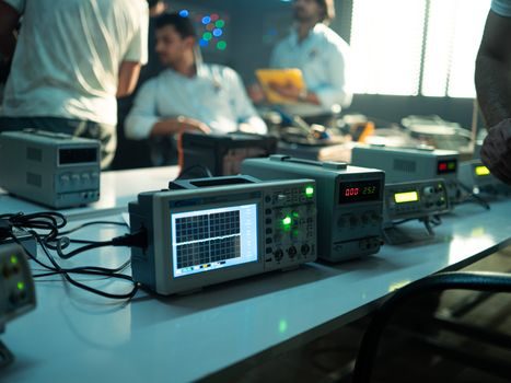
Signal calibrators fail in characteristic ways: the U8794's 25 V channel-to-earth rating means it cannot be connected directly to a 120 V or 230 V mains-referenced signal — applying mains across any output channel will damage the unit and is outside the specified operating envelope [S1]. A multi-channel calibrator is also a poor choice for high-bandwidth work; the U8794 is a DC simulation source, not a function generator, so AC waveform fidelity or pulse-edge simulation belongs to a different instrument class entirely.
Test leads fail from insulation cracking, broken conductors at the strain relief, and oxidized banana plugs. A worn lead with intermittent continuity will produce confusing readings on a DMM that the engineer may blame on the calibrator or the loop. The mitigation is routine replacement of leads and inspection of strain reliefs before each shift; the failure mode is mechanical, not electrical [S4]. Neither tool resolves ground loops, shielding problems, or noisy 4-20 mA runs — those need proper cable routing, signal conditioner selection, and isolators.
Standards, Sourcing and Field Discipline
Calibrator accuracy claims on a vendor datasheet are typically traceable to national standards through the vendor's own ISO/IEC 17025 calibration program, and the U8794's published specification of "Accuracy guaranteed for 1 year" is the vendor's recommended calibration interval [S1]. That interval — not the loop's commissioning date — should drive the calibration recall schedule on the bench. Test lead safety categories (CAT II / CAT III / CAT IV) are defined under IEC 61010 and are printed on the plug or probe body; using a CAT II lead on a CAT III measurement point is a specification violation regardless of how new the lead is [S4].
For sourcing, dedicated test leads manufacturers publish the conductor material (typically tinned copper or bare copper), insulation material (silicone for flexibility and high-temperature tolerance, PVC for cost), and current rating per lead, which lets the spec engineer match the lead to the loop's voltage and current envelope without overspending on overrated hardware [S4]. For a deeper look at how multi-channel signal sources and arbitrary waveform generators sit in the wider bench-instrument stack, see the Signal Calibrator Buying Guide 2026 or the related comparison on Signal Conditioner vs Thermostat: Function, Spec Gates and 2026 Selection Boundary.
Track two signals through 2026: first, the published accuracy interval on bench calibrators — if vendors start moving from a 1-year to a 90-day accuracy guarantee on multi-channel units, that raises the cost of ownership on every chassis [S1]. Second, IEC 61010 enforcement on lead categories in field service — tightened inspection regimes after a CAT-mismatch incident would push more sites to standardise on CAT IV 600 V leads as the default shop-floor issue [S4].