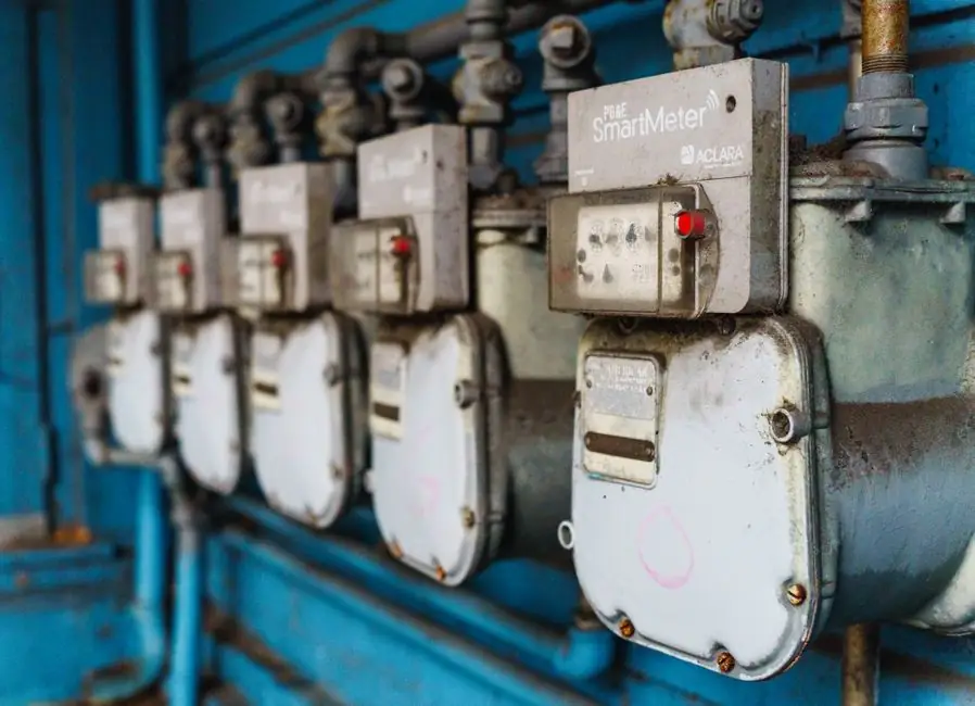
In hydraulic systems, 70% to 90% of wear and failure is contamination-related, and particle count data is the most direct way to flag the early-stage abrasive wear that destroys pumps, valves, and seals [S2].
Particle counting measures and reports the size and scope of particles in lubricating oil, and the result is mapped to the ISO 4406 cleanliness code so that operators can rank fluid against a published numeric target rather than guess at fluid health [S1]. The working channel is the same whether the sensor sits on a service truck, on a machine, or on a lab bench: particles in oil pass a detection zone and the instrument reports counts in bins such as 4 µm, 6 µm, 14 µm, and above.
Why Particle Count Is a Standalone CBM Signal
Particle count is treated as the most critical test in a used-oil analysis program because it catches abrasive wear before vibration, temperature, or pressure signatures appear, and it is the only routine test that produces an ISO code directly comparable against an OEM target [S1][S3].
Three measurement methods dominate hydraulic service: optical microscopy, automatic optical particle counting (white-light shadow or laser extinction), and pore blockage particle counting, where the pressure drop across a mesh screen is converted to a count via software [S1]. Light extinction is the most common method for mobile applications and is used in commercial products such as the MP Filtri ICS, which reports ISO 4406 codes and exposes data over CANbus [S4].
The decision variable is not "is it accurate" but "is the reading actionable" - that is, does the count reliably trend, and does it trigger a defined action (filter change, oil top-up, pull a sample for ferrography) before a pump fails.
Light-Blockage vs Digital Imaging vs Dynamic Imaging
Light-based sensors (white-light or laser) measure the shadow or extinction caused by a particle passing a detector, and are widely deployed because they are simple, affordable, and easy to calibrate, but they suffer from "phantom" particle counts when air bubbles or water droplets are misread as solids [S2].
Digital imaging sensors add image recognition software that filters out uniformly round bubbles and droplets from the count, and some implementations can infer the wear mechanism (sliding, cutting, fatigue) from particle shape, at the cost of higher price and more demanding calibration [S2]. Dynamic imaging particle contamination monitoring, standardised under ISO 21018-1, goes further and produces thumbnail images of every particle above 1 µm alongside the ISO 4406 code, so the operator can distinguish gels, fibres, metal debris, and water at the point of test [S5].
The pragmatic comparison in 2026: light-blockage sensors (legacy standard, calibrated to ISO 11171, cost-effective, but cannot tell a wear particle from an air bubble); digital imaging sensors (newer, bubble-tolerant, can hint at wear mode, priced higher); dynamic imaging analysers (ISO 21018-1 compliant, qualitative plus quantitative, suitable for source-of-contamination decisions, but still not universal in mobile equipment) [S2][S5].
ISO 4406, NAS 1638, SAE AS 4059: How to Read the Codes
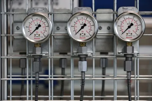
ISO 4406 reports three numbers - the cumulative count of particles per millilitre at three size thresholds (commonly 4 µm, 6 µm, and 14 µm) - and is the format most OEMs cite for hydraulic and lube circuits [S3][S4].
NAS 1638 (a US aerospace origin code) and SAE AS4059 (the US military aerospace successor) use class numbers tied to a count table, and are still seen in mobile and defence specifications; a particle counter on the bench typically outputs all three so the user can pick the one their OEM references [S3]. A useful working rule, grounded in published examples: a target of ISO 4406 18/16/13 is a common mid-tier cleanliness goal for industrial hydraulics, while servo and proportional systems usually demand tighter targets in the 16/14/11 range, and offline lab particle counters such as the STAUFF LasPaC-3-P deliver the bench data to verify whether a system is meeting that target [S3].
The decision variable here is not the code itself, it is whether the sensor output is mapped to the OEM-referenced code. Buying a sensor that only outputs NAS 1638 when the machine handbook calls out ISO 4406 18/16/13 is a process failure waiting to happen.
Inline vs Portable vs At-Line: Where the Sensor Lives
Inline particle counters are plumbed into the hydraulic circuit, deliver continuous data over CANbus or 4-20 mA, and are the form factor seen on mobile machines (e.g. the MP Filtri ICS), where the on-machine cost is reported at less than $1,500 per machine and is justified by reduced warranty exposure and unplanned downtime [S4].
Portable particle counters (such as the STAUFF LasPaC-3-P) are handheld units used for spot checks, route-based surveys, and verification of inline readings; they are fast, robust, and run off internal batteries, but only give a snapshot [S3]. At-line bench counters sit in a workshop or lab, require sample preparation, and are used for the deeper investigations where ISO 11171 calibration and a full ISO 4406 distribution are needed [S5].
For most plant managers in 2026, the answer is a hybrid: one or two inline sensors on critical assets (press, injection moulding, large mobile machines), a portable unit for route surveys, and an at-line bench counter tied to a sample-send schedule. The article on condition monitoring systems and the vibration condition monitoring primer are the natural complements, because particle count is one channel in a wider CBM stack that includes vibration, temperature, and pressure.
What Particle Count Does Not Catch
Particle counting cannot identify the chemistry of contamination, it cannot quantify water content below the saturation point, and a single high reading without a trend is hard to act on [S5].
Light-blockage sensors also have a hard time with the very small (< 4 µm) and very large (> 100 µm) end of the distribution, and traditional light-obscuration systems can clog on large particles, which is why dynamic imaging is now being positioned as a way to get the full size range plus the morphology needed to act on the reading [S5]. Hydraulic system health therefore depends on pairing the particle counter with at least one orthogonal test: Karl Fischer for water, FTIR or acid number for fluid degradation, and ferrography or spectroscopy for the wear-particle mode when a count is rising. As a UK plant-side note from 2026 puts it, "If you know the trend, you can plan the intervention; if you only have a snapshot, you are still reacting." [S7]
Selection Criteria and Sourcing Checklist
A buyer-side checklist drawn from the 2025-2026 practitioner literature: (1) confirm which cleanliness code the OEM requires and which the sensor actually outputs (ISO 4406 / NAS 1638 / SAE AS4059) [S3]; (2) decide on light-blockage, digital imaging, or ISO 21018-1 dynamic imaging based on whether you need to distinguish bubbles and droplets from solid wear [S2][S5]; (3) pick the form factor (inline CANbus/4-20 mA for continuous, portable for route, at-line for lab) and the magnetic particle tester or dust particle meter you will use to cross-check ferrous vs non-ferrous loading; (4) budget the on-machine hardware at roughly $1,500 per mobile machine for an inline light-extinction unit, and account for the higher price of imaging-based units [S4]; (5) confirm calibration traceability to ISO 11171 and a documented service interval.
For context on the wider power and process asset layer, the power monitoring system reference is the parallel channel that catches electrical and load-side faults a particle counter will not see, and pairing the two closes most of the blind spots in a single hydraulic bay. For an adjacent view of how monitoring choices cascade into wider industrial build decisions, the recent piece on compressed air audits, pressure-fault sizing, and real savings numbers is the closest cross-discipline analogue to a hydraulic contamination audit.
Trackable signals for the next planning cycle: ISO 21018-1 dynamic-imaging adoption rates on mobile OEM build sheets (still limited in 2026, but rising) [S5]; inline CANbus particle counters on Tier-1 mobile machines crossing the 1.5k USD cost threshold (already common in 2026) [S4]; and clearer OEM cleanliness targets expressed in ISO 4406 format in service manuals, which several UK plant operators report as still inconsistent across European and US mobile equipment suppliers as of mid-2026 [S7].