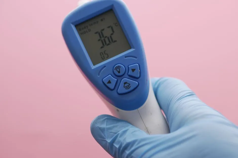
Two numbers on an industrial temperature sensor data sheet decide almost every buy: accuracy (how close the reading is to true temperature) and response time (how fast the output settles after a step change), with ifm's compact RTD transmitters publishing T05/T09 of 0.5/2 s and accuracy of ±0.54°F [S1].
The same two numbers are also where datasheet marketing and field behaviour drift apart the most. A sensor rated ±0.1°C in a lab bath can degrade to ±1.5°C once it is welded into a thermowell, sunk in a lagged pipe, and exposed to a 5 m/s process flow. Process engineers should treat the data-sheet pair as a starting point and re-derive the in-pipe error budget from the sensor, the well, the installation, and the electronics together.
Accuracy: the four contact technologies and where each one actually lands
RTDs (Pt100/Pt1000) are the accuracy benchmark for industrial contact measurement, with the standard platinum cell usable from -200°C to +850°C and Class A tolerance delivering around ±0.15°C at 0°C [S2][S3]. Thermistors are tighter still in their narrow band, with calibrated NTC types reaching ±0.05 to ±0.2°C between roughly -50°C and +150°C, which is why medical and HVAC OEMs prefer them [S5]. Thermocouples trade that precision for range, with K-type spanning -270°C to +1800°C and common accuracy around ±1.5°C, plus a cold-junction compensation error that must be added to the published figure [S2][S5]. Digital IC sensors such as the TI LMT90 are specified at ±3°C maximum over -40°C to +125°C, which is acceptable for cabinet and panel monitoring but not for closed-loop process control [S8].
Response time: T05/T09 is the only spec worth comparing
Manufacturers do not all define response time the same way, and that is the first trap. ifm's published table reports T05/T09, the time to reach 50% and 90% of a step change, and the same format is used across the ifm range from 0.5/2 s on the TA industrial compact transmitter to 10/40 s on the TA flush sanitary design [S1]. SOR's SSi catalogue also quotes response time directly, with its Class A RTD assemblies targeting fast step response for demanding accuracy applications [S3]. Engineers specifying for a steam line or a Safety Instrumented Function (SIF) should reject any data sheet that lists only "time constant τ" without naming the step and the medium, because τ is roughly one-third of T09 and the two are routinely confused [S5][S7].
Selection by application: ifm's published matrix as a working example

ifm's "Select by Application" tool organises its temperature range into nine families with explicit accuracy, response, pressure and output data, which is a useful template even for non-ifm buyers [S1]. Sanitary compact transmitters (Type TA) sit at -50 to +150°C, 100 to 160 bar, 4-20 mA or IO-Link, with 0.5/2 s and ±0.54°F. The TCC smart diagnostic transmitter tightens accuracy to ±0.36°F over -25 to +160°C at 250 to 400 bar, but slows to 1.5/4 s because of its heavier thermowell. Infrared (Type TW) breaks the contact-only assumption with 0 to +2500°C range and "various" response, useful for moving rollers, busbars and furnace tubes where a contact probe cannot survive [S1].
Criteria-based comparison: choosing between RTD, thermocouple, thermistor and IR
Against four decision criteria (range, accuracy, response, environment), the four contact and non-contact families line up as follows. RTDs win on accuracy and long-term stability over a moderate -200 to +850°C range, with a slower response than a bare thermocouple [S4]. Thermocouples win on range and cost, with K-type covering -200 to +1200°C in oxidising atmospheres and bare-junction designs giving the fastest step response of any contact sensor [S2][S5]. Thermistors win on accuracy in a narrow -50 to +150°C window, where their small bead size also gives the fastest response in still air or still water [S2][S5]. Infrared/pyrometers win on non-contact measurement of moving or hazardous targets between -50 and +3000°C, but only when surface emissivity is known and the optical path is clean [S5]. Engineers who need both accuracy and survivability in a high-pressure process almost always end up specifying an RTD inside a thermowell, accepting the thermal lag as the cost of mechanical protection [S3].
Installation effects that quietly destroy the data-sheet numbers

Three installation factors routinely wipe out a sensor's published accuracy and response time. First, thermowell lag: a heavy stainless thermowell in a lagged pipe can stretch a 0.5/2 s T05/T09 to several seconds of T09, which is why ifm's flush TA design is only 1/3 s in the data sheet but 10/40 s once the sanitary tri-clamp body is fitted [S1][S3]. Second, self-heating in thermistors and low-current RTD designs, where the measurement excitation current itself warms the element by 0.1 to 1°C, an error that scales with the square of the excitation [S5]. Third, lead resistance on 2-wire RTDs, where every 1Ω of uncompensated lead adds roughly 2.6°C at Pt100, which is why 3-wire and 4-wire Pt100 hookups are the default for any accuracy claim tighter than ±1°C [S4][S7]. Process engineers should also remember that the 4-20 mA loop, HART and IO-Link outputs add their own quantisation and update-rate limits on top of the sensor's own noise floor, a fact that matters in SIL-rated loops where the safety PLC samples at fixed intervals [S5].
Standards, sourcing and the right next check
For Pt100 elements, IEC 60751 defines the nominal 100.00Ω at 0°C and the 0.00385 Ω/Ω/°C alpha, and is the standard every accuracy claim should reference, with more detail in the 2022 update covered in Pt100 tolerance and the IEC 60751 vs ASTM E1137 update. For an industrial-grade RTD Pt100 probe, the typical Class A tolerance is ±(0.15 + 0.002·|t|)°C, which gives roughly ±0.35°C at 100°C and is the figure SOR's Class A assemblies are built to meet [S3]. Buyers comparing data sheets should lock the spec to three numbers only: IEC 60751 Class, T05/T09 in the actual process medium, and output protocol (4-20 mA, HART, IO-Link), and should then request a calibration certificate traceable to a national lab rather than relying on the marketing brochure. The next sensible cross-check is the dual-input redundancy story in dual-input temperature transmitters, which addresses how the same accuracy and response numbers behave when a second element is added for SIL 2/3 voting.