An effective alert-to-work-order integration helps address the P-F planning window by rapidly routing a validated condition alert into an assigned maintenance task [S1][S2].
The integration follows four stages: Sense, Detect, Route, and Act [S2]. Predictive-maintenance technologies such as vibration analysis, thermal imaging, ultrasonic testing, and oil analysis are often used to gather equipment-condition data [S5].
Alert-to-Work-Order Control Path
The operational unit is not an alert, but an executable work order. A mature flow starts with sensor data, passes through detection and routing, and ends with a completed repair whose outcome returns to the predictive system [S1][S2].
Use this controlled sequence:
Ingest readings from the monitoring platform or third-party sensors, including vibration, temperature, and amperage data [S4].
The system interprets sensor data, determines the required action, and delivers it to plant-floor personnel in an immediately executable format [S1].
3. Validate and classify the condition, recording severity, probable failure mode, and asset location [S3][S4].
4. Create or update a CMMS work order with diagnostic evidence, procedure, labor requirement, parts, priority, and due date [S1][S6].
5. Assign, execute, close, and verify the task using post-maintenance sensor readings [S4].
Attach the asset, fault, severity, and reading to the generated work order [S2].
Choose the Integration Architecture
Three integration patterns suit different plant constraints: native CMMS integration, an integration hub or API, and manual work-order creation. The correct choice depends on alert volume, asset criticality, sensor variety, and the need for closed-loop verification [S3][S4].
Use manual transfer between a PdM platform and a CMMS/EAM only as an interim approach, because manual transfer is inefficient, prone to errors, and slows response times [S3].
Design the Work-Order Payload
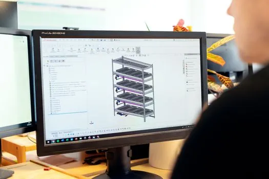
A useful CMMS work order must carry enough diagnostic and maintenance context for a technician to begin diagnosis without searching across dashboards, email threads, and repair histories [S1][S6].
Populate the work order with supported asset, fault, severity, and reading information [S2].
1. Asset identity and hierarchy location.
2. Source system and unique alert ID.
3. Severity, priority, and rule or threshold that fired.
5. Suspected failure mode, such as bearing wear, imbalance, misalignment, looseness, overheating, or abnormal motor current [S2].
6. Recommended inspection and repair procedure.
Assign the appropriate technician and track the task through completion [S1].
9. Parts list with stock position or reservation status [S4][S6].
10. Completion evidence, including findings, parts used, and post-repair condition reading [S3][S4].
Use stable identifiers rather than free text. The asset ID must match the CMMS asset hierarchy, and the alert ID must prevent duplicate work orders during retries. The integration guide for CMMS asset hierarchies provides the structural context for this mapping: asset hierarchy in a CMMS.
Route, Prioritize, and Assign Work
An alert should become work only after deduplication, severity assessment, and rule validation. Automatic creation without triage can flood planners with duplicate or low-value events, while unsupported manual triage consumes the warning window [S2][S4].
Apply 4 routing controls:
Use asset criticality, detected fault mode, measured severity, and production exposure to establish work-order priority [S3]. Check parts availability before dispatch, then assign a technician by skill and availability [S5]. Put urgent failures in an immediate-response queue, while confirmed degradation can be planned into an agreed production window [S3].
Verify Repairs and Close the Loop

Closing a work order in the CMMS does not close the predictive-maintenance loop by itself. The completion record must return to the condition-monitoring platform so that the next alert reflects the confirmed repair outcome [S3][S4].
The integration should close the loop from sensor insight to completed repair [S1][S4].
Compare at least 3 records: the alarm reading that triggered the work order, the reading after repair, and a subsequent steady-state reading after the asset returns to service. Record whether the alert cleared, recurred, or escalated. Recurrence within a defined observation period should initiate engineering review of the detection rule, repair quality, or recurring failure mode.
Track 4 operational measures: alert-to-work-order latency, percentage of alerts assigned without manual transcription, percentage of completed jobs with post-repair readings, and repeat-alert rate after closure. These measures connect implementation quality to completed maintenance rather than alert volume [S1].
Control Failure Modes and Interfaces
The most common integration failure is an alert that remains visible only in a monitoring dashboard. A second failure is a valid CMMS work order that lacks diagnostic context, parts, or ownership; both consume the interval between early detection and functional failure [S2][S3].
Test 6 failure cases before production release:
Duplicate delivery must return the existing work order. A missing asset match must create an exception record, not a generic work order. A missing sensor value must block automatic closure. A failed CMMS write must enter a retry queue with error visibility. An out-of-stock critical part must generate a planning escalation. A persistent abnormal reading after repair must reopen the task for engineering review [S3][S4][S6].
Set integration ownership across operations technology and information technology. OT owns sensor identity, units, timestamps, and signal quality; IT owns API credentials, endpoint security, retries, and interface monitoring. The CMMS remains the system of record for work orders, labor, parts, and completion history, while the monitoring platform remains responsible for condition diagnostics [S3][S4].
Select Sensors and Monitor the Right Failure Modes

Predictive alerts are useful only when the selected sensing method matches the failure mode and the alert is converted into a resource-backed intervention. Common industrial methods include vibration analysis, ultrasound, oil analysis, infrared thermography, motor-current signature analysis, and process-sensor trending [S2][S5].
Vibration can identify imbalance, misalignment, looseness, and bearing wear, and ISO 20816 severity zones provide the referenced evaluation framework [S2]. Oil analysis evaluates wear metals, viscosity, and contamination against ISO 4406 cleanliness classes [S2]. Infrared thermography identifies hot spots on bearings, motors, and electrical connections. Ultrasonic and acoustic methods can expose early bearing friction, lubrication starvation, leaks, and arcing [S2].
Use process sensors for temperature, pressure, flow, and speed trends when those variables define the asset's operating risk. Motor-current signature analysis can inspect rotor-bar, winding, and load faults without adding a shaft-mounted sensor [S2]. Each method has a different warning profile, so the integration design must preserve the source measurement, unit, timestamp, and rule instead of reducing every event to a generic status flag [S3][S4].
Track 3 implementation signals: median elapsed time from alert timestamp to CMMS acceptance, percentage of work orders populated with the required 10 fields, and percentage of completed jobs with post-repair measurements. Use these signals to tighten rules before increasing automation coverage.