
Internal ring gears paired with an external pinion transmit 20-50% more torque than a comparably sized external gear pair, because the convex pinion tooth engages a concave ring tooth, producing a larger contact patch and lower Hertzian stress [S1].
The geometry comes with hard constraints: internal teeth cannot be hobbed (the cutter has no access to an internal tooth space), so production runs on gear shapers, broaches, or power skiving, and the part price runs roughly 30-40% above an equivalent external gear [S1][S2]. For compact drives that price is usually recovered through smaller envelopes, higher torque density, and coaxial same-direction output.
Geometry and Meshing Direction: Why a Ring Gear Spins the Same Way as the Pinion
An internal gear is a hollow ring with teeth cut on its inside diameter, meshing with a smaller external pinion that sits inside the bore; both members rotate in the same direction, the opposite of a standard external-external pair [S2][S3]. That same-direction rule is the geometric reason planetary gear sets can use a coaxial layout: the sun, planets, and ring all share one axis instead of stacking idler gears to reverse rotation [S2].
Center distance for an internal pair is the difference of the two pitch radii, not the sum. With module m, pinion teeth z1, and ring teeth z2, the operating center distance is a = m*(z2 − z1)/2 [S2]. Because z2 − z1 is much smaller than z1 + z2, the same ratio fits in a much shorter axial footprint, which is the main reason planetary reducers quote 30-50% size reduction versus equivalent external gear trains [S1].
Load Capacity: Convex-Concave Contact vs Convex-Convex
External gear pairs put two convex tooth flanks against each other, narrowing the contact patch and pushing Hertzian contact stress up. Internal pairs put a convex pinion flank into a concave ring flank, conforming the contact and dropping peak stress for a given load [S1].
Concretely, AGMA-style bending and contact ratings for an internal pair typically land 20-50% above an external pair of the same module and face width, with the gain concentrated in the pitting-resistance side of the rating rather than the bending side [S1]. This is also why ring gears show up in high-torque, low-speed units (planetary wheel drives, robot joint actuators, helicopter transmissions) where pitting life, not tooth-bending fatigue, is the limiting mode.
Profile geometry is not a simple mirror image: the internal tooth addendum is shortened relative to the external tooth addendum to clear the pinion tip, and the pinion must carry enough teeth-difference to avoid internal tooth interference. A common rule of thumb from older AGMA reference data: for 20° pressure angle, keep the difference (z_ring − z_pinion) at or above 12; for 14.5° pressure angle, keep it at or above 15, with undercut appearing below 32 teeth at 14.5° PA and below 18 teeth at 20° PA [S4].
Manufacturing Reality: Shapers, Broaches, and Skiving vs Plain Hobbing
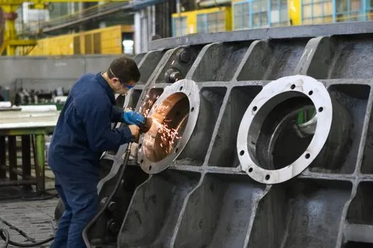
External gears are produced on standard hobbers, shapers, or milling machines with open tool access; internal gears cannot be hobbed at all, because a hob worm has no way to reach inside a bore to cut the tooth space [S1][S5]. The standard process is CNC gear shaping on machines such as the Liebherr LORENZ LS 156 or Fellows 36-6, with broaching and power skiving as the alternatives for higher-volume production [S5].
That access limitation drives inspection cost as well: a profilometer or pitch-measuring machine has to reach inside the bore, so inspection cycle time on an internal gear is typically 1.5-2x that of an equivalent external gear, even when AGMA quality class is the same [S5]. Specialty work like internal gear grinding exists but has tight equipment constraints, and most shops hold tight tolerances through shaping process control rather than post-shaping grinding [S5].
Selection Matrix: External vs Internal for a Compact Drive
For a compact drive decision, four criteria usually decide the call: torque density, envelope, cost per piece, and tool/inspection access. [S3]
On torque density, internal pairs win: 20-50% higher load capacity at the same module and face width thanks to the convex-concave contact [S1]. On envelope, internal pairs also win: 30-50% smaller footprint at the same ratio, and coaxial output (no idler) simplifies the shaft layout [S1][S2]. On cost per piece, external pairs win, at roughly 30-40% lower part cost and standard hobbing that any gear shop can run [S1]. On tooling and inspection access, external pairs win again, because internal work needs shaping, broaching, or skiving capacity plus internal-reach inspection [S5].
Choose internal (ring) gears when the drive is planetary, epicyclic, or a robotic/aerospace joint actuator, where the torque density and same-direction rotation justify the shaping-only production route [S3][S5]. Choose external gears for parallel-shaft reducers, general industrial gearboxes, and any high-volume build where hobbed external teeth keep unit cost and lead time down [S1][S3]. A useful diagnostic: if the design already needs a reversing idler or a wide-spaced parallel-shaft layout to hit the ratio, an internal pair will usually shrink the package; if the design is a single-stage parallel-shaft reducer with no coaxial constraint, external gears are almost always the lower-cost answer.
Standards, Materials, and Inspection Anchors
Gear geometry and quality for these meshes are typically referenced against the AGMA quality class system (e.g. AGMA 2000 / 2015 for rating, AGMA 908 for inspection), with involute profile, lead, and tooth-thickness tolerance checked on a gear checker or CMM-based analytical gear inspection [S5]. For module and diametral pitch, internal gears from custom shops are usually quoted in either metric module m or imperial diametral pitch DP, and the mating pinion has to be specified in the same system to avoid a tooth-system mismatch [S5].
Material selection for ring gears in compact drives is dominated by through-hardened alloy steels (e.g. 4140, 4340) for high-cycle applications, case-carburized steels (e.g. 8620) for the ring when pitting resistance is critical, and stainless or specialty alloys for corrosive or aerospace environments; INSCO's published internal-gear material list explicitly includes steel, stainless, alloy steel, and specialty materials, with AGMA quality class set per application [S5]. Heat treatment and case depth are usually the deciding variables for pitting life, not the choice of internal vs external geometry, but case depth control is harder on internal teeth because the induction or carburize cycle has to reach the inside diameter uniformly.
Failure Modes and Common Pitfalls
The three failure modes to design against on internal pairs are: (1) internal-tooth interference from a too-large pinion, which shears the addendum off the ring tooth, (2) inadequate contact ratio, which shows up as vibration and noise at higher speeds, and (3) pitting or micropitting on the ring tooth flank when lubricant viscosity or surface finish is undersized for the Hertzian load [S1][S2][S4].
Interference is caught at the drawing stage: keep (z_ring − z_pinion) at or above the AGMA-recommended minimum (12 at 20° PA, 15 at 14.5° PA), and apply addendum shortening on the ring tooth to clear the pinion tip [S4]. Contact ratio on internal pairs is usually higher than on equivalent external pairs because the addendum is shorter and the operating pitch diameters are closer together, but it can still drop below 1.4 if the face width is too narrow for the module, so check ε as part of the rating, not just bending and contact safety factor [S2]. Pitting is mitigated the same way as on external gears: surface finish in the 0.4-0.8 Ra range, adequate lubricant viscosity for the pitch-line velocity, and a case-hardened ring with effective case depth at least 1.5x the maximum Hertzian depth of penetration.
For related shaft-component selection, the bearing arrangement is the easy place to lose the gain: a compact drive built around an internal ring gear still needs a properly sized bearing on each end of the pinion shaft, and a mismatched bearing is the most common reason a theoretically high-torque-density drive underperforms its rating. Spec-driven bearing sizing is covered in How to Read a Ball Bearing Dimension Series Code; for the surrounding drive architecture the same logic of matching the load path to the housing stiffness applies to gear coupling selection on the output side.
Trackable Signals for the Next 6 Months
Watch the AGMA quality class on ring-gear prints: more aerospace and robotics builds are quoting AGMA 12+ on internal gears in 2026, and that pushes the shop toward shaping plus analytical inspection rather than shaping plus a lighter roll-check [S5]. Watch power-skiving machine sales: as skiving cycle times come down, expect the cost gap between internal and external gears to compress from the current 30-40% toward 15-20% on module 1.5-3 production [S1].
A practical next step: pull the existing parallel-shaft reducer prints, mark up the center distance and the bearing span, and rerun the ratio with an internal pair at a = m*(z2 − z1)/2; if the new center distance is 30-50% shorter and the bearing dynamic load rating still clears the new radial load, the internal-gear conversion is usually worth the shaping-only sourcing constraint [S1][S2].
Component reference pages worth checking: steel mesh, and mesh belt conveyor.