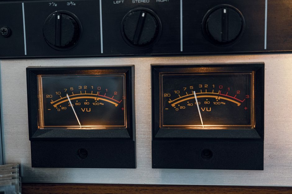
An LCR meter is an AC impedance analyzer for passive components, with 2026 bench models spanning 10 Hz-200 kHz test frequency and basic accuracies from ±0.05% to ±0.08% [S2][S4]. A signal calibrator is a DC process-loop source/readout for current (typically 4-20 mA) and voltage spans used in field instrumentation [S1].
They share an LCD and a four-wire Kelvin lead on the benchtop, but they do not substitute for each other: an LCR meter cannot source 24 V loop power, and a signal calibrator cannot measure Q-factor of an inductor at 1 kHz. Picking the wrong one costs hours and produces invalid data, not just wrong numbers.
Core Function and Measurement Domain
LCR meters characterize passive components by applying an AC stimulus at a user-set frequency and reporting impedance-derived parameters: L, C, R, plus Q (quality factor), D (dissipation), ESR (equivalent series resistance), and θ (phase angle) [S5]. The 2026 MICROTEST 6365/6365A line covers 10 Hz-200 kHz, with the 6365A variant extending the low end to 0.1 Hz for measuring large-capacitance aluminum electrolytics in UPS and EV battery packs [S2][S7].
Signal calibrators operate in the DC process domain: they source and measure 0-20 mA / 4-20 mA current loops and 0-10 V / ±10 V voltage spans, simulating a transmitter or reading a controller output. They are the reference instrument for commissioning pressure transmitters, validating signal isolators, and trimming loop calibrator field setups, where accuracy is stated as % of span plus µA or µV offset.
Test Signal: AC Impedance vs DC Process Current
The defining engineering difference is stimulus type. An LCR meter drives an AC sine (typically 100 mV-1 V RMS, optionally 1-2 V) at frequencies from a few Hz to MHz on a high-impedance measurement port, then solves for the chosen parameter model (series or parallel equivalent circuit) [S5].
A signal calibrator drives or measures a DC quantity that mirrors a 4-20 mA HART or 0-10 V analog process signal, often with simultaneous read-back of the loop current. There is no frequency sweep, no Q-factor, and no equivalent-circuit model. The two instrument classes share the four-wire Kelvin concept but apply it to entirely different physical quantities.
Selection Criteria and Spec Comparison
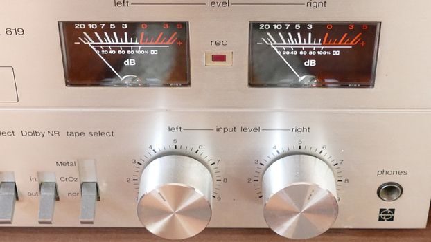
Choose by primary use case, not by instrument class. A maintenance technician validating a 4-20 mA level transmitter needs a signal calibrator; a QA technician sorting 0805 MLCCs at 1 kHz needs an LCR meter. The two are complementary in a well-equipped lab, not interchangeable. [S1]
Decision criteria, lined up for a side-by-side read:
1. Stimulus: LCR = AC sine, 10 Hz-200 kHz typical (6365A goes 0.1 Hz-200 kHz) [S7]; Signal calibrator = DC, 0-20 mA / 0-10 V, 24 V loop supply typical.
2. Primary readout: LCR = L, C, R, |Z|, Q, D, ESR, θ; Signal calibrator = mA, V, % of span, sometimes mV/°C for RTD/T/C simulation.
3. Accuracy statement: LCR = basic impedance accuracy ±0.05% (6363/6364) to ±0.08% (6365/6365A) [S3][S7]; Signal calibrator = % of span + floor (e.g. 0.01% + 1 µA), specified at 23 °C ±5 °C.
4. Connectivity: LCR = RS-232, GPIB, USB Host, Handler, LAN, optional PC plotting software [S3]; Signal calibrator = HART modem on some units, no GPIB/Handler typical.
5. Price band: an entry 10 Hz-20 kHz bench LCR (TH2810D) lists at $509 single-unit, $450 at ≥5 quantity [S1]; industrial multifunction signal calibrators generally run higher once HART and pressure modules are included.
Workflow and Use-Case Fit
LCR work sits on the component bench: incoming inspection, production line sorting, R&D characterization, and reliability QA. The MICROTEST 6363/6364 economic series at 10 Hz-20 kHz with ±0.05% basic accuracy and four simultaneous parameters on the LCD handles most MLCC, inductor, and resistor screening [S3].
Signal calibrator work sits in the field or on a DCS commissioning bench: loop check, valve positioner trim, transmitter calibration, and signal conditioner validation. Neither workload is served by the other instrument, and a shop that buys an LCR to commission loops will fail every acceptance test.
Vendor and Model Landscape in 2026
The 2026 LCR market is dominated by three brand clusters: MICROTEST (Taiwan) with the 6363/6364/6365/6365A series at 10 Hz-200 kHz and ±0.05%-±0.08% [S3][S7]; Wayne Kerr (UK) with high-end precision impedance analyzers plus Danbridge (Denmark) covering high-voltage and high-resistance passive-component test [S6]; and ZXP (Shenzhen) fielding the ZX8531 at 50 Hz-200 kHz with ±0.05% basic accuracy and a color TFT display, positioned as data-comparable with Keysight and Wayne Kerr units [S4].
Portable 10 kHz LCRs from Tecpel (LCR-614) extend the category to handheld field use with simultaneous primary/secondary parameter display on a backlit LCD, suited to field service rather than lab QA [S8]. Signal calibrator vendor rosters differ entirely and center on process-instrumentation brands rather than passive-component-test houses.
Limitations, Failure Modes, and Common Spec Traps
An LCR meter will give nonsensical readings on an active loop, because its AC stimulus is not loop-compliant and the DUT must be a passive, de-energized component. Equally, a signal calibrator cannot read inductance, and any reading labeled in henries from such a unit is a misconfiguration, not a measurement. [S1]
Spec traps on LCR purchases: (a) basic accuracy ±0.05% applies to R and C at a narrow frequency window, not across the full 10 Hz-200 kHz range; (b) 4-wire Kelvin clips are required to hit the headline number, 2-wire alligator leads will degrade by an order of magnitude; (c) economy models like the 6363 cap at 20 kHz, so any application needing 100 kHz+ on ceramic capacitors needs the 6365/6365A [S2][S3][S7]. Spec traps on signal calibrators center on span drift, burden-voltage on current loops, and HART compatibility, none of which an LCR datasheet addresses.
Sourcing Standards and Engineering References
LCR meter traceability typically follows IEC 61010 for instrument safety, with calibration standards tied to known LCR reference standards at 100 Hz, 1 kHz, 10 kHz, and 100 kHz. Signal calibrator traceability follows the process-instrumentation chain (IEC 61298 for process measurement and control devices) and the loop-power / HART protocol layer for signal isolator work. [S1]
Engineers comparing Thermostat vs Signal Isolator decision logic will see the same instrument-class-vs-application split applied to temperature loops; the LCR-vs-signal-calibrator question is the impedance-domain version of that same decision. The next trackable signal is the 6365/6365A successor datasheet release from MICROTEST and any 2026 Q3 update to the ZX8531 firmware at ZXP, both of which will reset the price/accuracy envelope in this segment.