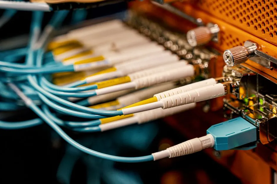
Liquid cooling is becoming a practical thermal-management option for high-density power electronics as chip heat loads approach 4,000 W and rack-scale systems move toward 1 MW [S3].
The same cold-plate, dielectric-loop and immersion principles used in AI infrastructure can serve converters, inverters, drives and other industrial equipment, but component reliability, coolant compatibility and serviceability determine the viable architecture.
What Liquid Cooling Changes in Power Electronics
Liquid cooling removes heat at the device or enclosure surface rather than relying only on air moving across a heatsink. In an air-cooled design, the heat path depends on a semiconductor package, an interface material, a solid heatsink, conduction into airflow and then facility-side heat rejection. A liquid loop can shorten the longest thermal section by carrying heat directly from a cold plate into a coolant circuit. [S3]
The physical advantage is substantial. That does not make every converter more efficient, but it gives designers a way to handle concentrated losses within a much smaller package.
This matters beyond servers because power-electronic equipment is often designed around switching devices, busbars, magnetics and heat sinks rather than a rack of processors. A compact inverter can concentrate heat in one semiconductor bridge, while an industrial drive may need a heat sink large enough to dominate the enclosure. Liquid cooling allows that thermal resistance to be divided between the package, the cold plate and the loop, rather than concentrated in a finned block and room-sized air path.
The decision is not simply liquid versus air. For a low-loss controller in a 24 V cabinet, pumped liquid may add cost, leakage points and controls without producing a useful return. For a high-power converter with concentrated semiconductor heat, a coolant path can reduce the physical size of the heat-rejection assembly and may support a more compact electrical layout.
Selecting the Cooling Architecture by Heat Load
Single-phase direct-to-chip cooling circulates water through cold plates while the coolant remains liquid. In power electronics, the equivalent architecture places a cold plate against an IGBT module, MOSFET, SiC device, diode or precision heat-spreading assembly. The coolant then carries heat to a heat exchanger, chiller or heat-rejection loop.
Two-phase direct cooling allows the working fluid to boil at the device interface. Heat then enters the vapor stream, and a condenser returns the fluid to its liquid state.
Immersion cooling places the assembly in an electrically insulating dielectric liquid. Single-phase immersion keeps the fluid liquid, while two-phase immersion permits boiling. In data centers, the liquid can cool multiple boards without individual cold plates, but power electronics still needs a defined path for busbars, connectors, windings and other components that cannot safely operate in an unrestricted bath.
A direct comparison highlights the practical differences:
In two-phase immersion cooling, a server is submerged in liquid that actively boils next to heat-producing components and cools them in the process.
Where Liquid Cooling Creates Value Outside IT
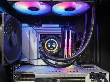
Energy-storage converters face a related constraint: their power semiconductors operate close to electrical equipment, and the enclosure must also provide isolation, fire protection and access. A compact liquid loop can separate heat removal from the air path, allowing the converter section to retain its designed electrical clearances rather than being enlarged by large finned heat sinks.
Industrial motor drives benefit when regeneration, overload duty and short-term power peaks produce transient heat loads that are awkward for air systems to absorb. A cold plate with a controlled coolant flow can maintain lower junction temperatures than passive conduction alone and can permit smaller power modules. The thermal case becomes weaker where the drive operates at low loss for most of its life, because pumps, sensors and fluid maintenance then add operating items without delivering a proportional capacity benefit.
Fast-charging equipment is another credible use because high power conversion is concentrated in a compact enclosure. The data-center technology transfer is architectural rather than literal: a data-center cold plate cools processor heat through a facility-water or dielectric loop, while an industrial charger generally requires a closed glycol or dielectric loop, pumps, filtration and heat rejection suitable for a public or industrial environment.
Waste-heat recovery can extend the economic case. A review of emerging semiconductors through data centers identifies liquid cooling and waste-heat recovery as linked technologies needed to support broader decarbonization [S7]. For industrial sites, recovered heat may support building heating or process loads, but that business case depends on operating hours, temperature matching and local heat demand rather than cooling hardware alone.
Reliability, Fluids and Service Constraints
Coolant compatibility is a material-selection problem, not a pumping decision. Water offers high heat capacity, but it requires corrosion control, freeze protection where applicable, treatment of impurities and deliberate isolation from electrical parts. Dielectric fluids can reduce electrical-clearance constraints, yet their temperature range, viscosity, aging behavior and material compatibility must be checked against every wetted seal, hose, gasket and insulation component. [S4]
Leak prevention starts with the cooling loop architecture. A full-flow or sectionalizing arrangement can isolate a failed heat exchanger or pump, while pressure monitoring, temperature sensing and conductivity or leak detection provide alarms before fluid reaches energized components. These controls are not optional for high-voltage equipment because the consequences of leakage differ from those of a small air-cooling failure.
Reliability remains the principal barrier to broader adoption. The IEA 4E EDNA report identifies lack of standardization, high initial cost and long-term reliability concerns as reasons liquid-cooling use in data centers remains limited. Its modeled energy-saving potential is approximately 8% at server level, 30–40% at facility level and 10–21% overall [S2]. Those data-center figures should not be transferred directly to industrial equipment, where auxiliary loads, bypass air, process heat and equipment duty cycles differ.
Maintenance also changes. Air-cooled systems often expose filters, fans and heat sinks as routine service points. A liquid system adds pumps, seals, sensors, fluid quality checks and possibly a condenser or chiller. A spare-parts strategy should therefore cover both electrical and hydraulic failure modes, and service procedures should define fluid sampling, refill procedures and isolation procedures before deployment.
The related comparison of immersion cooling and direct-to-chip deployment is useful because the same implementation barriers recur outside data centers: cold plates preserve familiar service boundaries, while immersion changes the enclosure, electrical interface and replacement workflow.
From Data-Center Hardware to Industrial Qualification
Liquid cooling should enter an industrial power-electronics project through a thermal and reliability review, not through a copied server-rack design. The first step is to quantify component loss, hotspot temperature, allowable coolant temperature, pressure, fluid chemistry and required heat-rejection capacity. The second is to decide whether the heat load justifies a pumped circuit rather than an optimized air-cooled assembly. [S3]
The third step is a qualification plan covering cold-plate adhesion or mounting pressure, electrical isolation, fluid-material compatibility, pressure testing, leak detection, pump redundancy and thermal transients. The fourth is service validation: technicians must be able to isolate one unit, diagnose flow and temperature faults, sample or replace fluid where needed, and return the converter to service without rebuilding the entire cooling installation.
External reference designs can shorten this process. One liquid-cooling blueprint co-developed with NVIDIA scales to 227 kW per rack, demonstrating how heat capture, distribution and rejection must be designed as one architecture [S4]. The transferable lesson for industrial power electronics is that cold plates alone do not solve thermal management. Pumps, heat exchangers, controls, piping, expansion or pressurization strategy, and facility integration determine whether the system remains reliable.
Trackable procurement signals include the share of tenders that specify a coolant chemistry, maximum pressure, allowable temperature range and leak-detection interface, rather than only a cooling capacity. At the equipment level, requests for redundant pumps, replaceable cold plates, fluid sampling points and explicit warranty conditions for wetted components will show whether suppliers are moving from demonstration hardware toward qualified industrial products.