A microprocessor protection relay samples CT and VT secondary quantities, converts them into numbers several times per power cycle, and runs the protection logic in software.
These digital devices combine multiple functions in one compact case, from ANSI 50 and 51 overcurrent elements to ANSI 87 differential, ANSI 21 distance, and ANSI 49 thermal protection [S2].
What defines a microprocessor protection relay
A microprocessor-based protective relay is a digital device that acquires secondary current and voltage, performs analog-to-digital conversion, applies numerical algorithms, and issues trip commands through software-controlled logic [S2].
The practical distinction from an electromechanical relay is the removal of springs, induction discs, and fixed analog comparison circuits from the decision path [S2]. A numerical relay is also microprocessor-based, so “digital relay” and “numerical relay” often describe the same technology rather than two separate hardware families [S3][S6].
Relays in this class can also be described as multifunction devices because one hardware platform supports several protection elements, subject to the installed firmware and licence [S1][S2]. For engineering selection, the relevant microcomputer protection classification is not generation alone, but the protected equipment, required ANSI functions, timing characteristic, and communication requirement.
Classification by protection function
Common overcurrent classifications include instantaneous, definite-time, and inverse-time elements, while distance-protection families include impedance, reactance, and mho characteristics [S5]. ANSI function 21 identifies distance protection, function 27 identifies undervoltage protection, and function 50 identifies instantaneous overcurrent [S3].
Microprocessor platforms combine six widely used groups in one enclosure: ANSI 50/51 phase and earth-fault overcurrent, ANSI 67 directional overcurrent, ANSI 87 differential, ANSI 21 distance, and ANSI 49 thermal protection [S2]. The operating principle differs by function: overcurrent compares measured magnitude with a threshold, directional overcurrent adds phase-angle supervision, differential compares currents across a protected zone, and distance estimates apparent impedance from voltage and current [S2].
The protected asset determines the functional set. A transformer commonly requires differential, restricted earth-fault, overcurrent, and thermal functions; a feeder generally needs directional and non-directional overcurrent plus earth-fault elements; a motor requires phase-fault, earth-fault, and thermal overload protection; and a generator can require differential, loss-of-excitation, overcurrent, and other machine-specific functions [S2][S4].
Classification by operating characteristic

Overcurrent elements divide into instantaneous, definite-time, and inverse-time types, with inverse-time curves coordinating selectivity through intentional delay as fault magnitude changes [S5]. Instantaneous operation provides the fastest response for high-magnitude faults, definite-time operation applies a fixed delay, and inverse-time operation reduces delay as fault current increases [S5].
Distance elements are classified by the impedance characteristic they impose: impedance, reactance, and mho relays represent different geometric approaches to apparent-impedance measurement [S5]. ANSI 50, 51, 50N, 51N, 67, 87, 21, and 49 are not competing relay generations; they are functional elements that may coexist in the same microprocessor chassis [S2].
This functional-versus-technology distinction prevents a common specification error. Selecting only by the label “digital relay” leaves the protection philosophy undefined, because the same microprocessor platform can implement several characteristics. The settings file must identify each element, pickup value, time curve, directional status, and reset behavior rather than naming only the relay family [S2][S5].
Digital versus electromechanical and static relays
Electromechanical relays use electromagnetic operating principles and induction-disc, electromagnet, induction-cup, or balance-beam measuring elements; static relays use transistors and analog integrated circuits; and digital and numerical relays use microprocessors, digital integrated circuits, and digital signal processors.
Programming differs more clearly than the device label: electromechanical relays use plug or dial settings, static relays may use thumbwheel or switch settings, and digital and numerical relays support keypad or computer programming [S3]. Event or disturbance recording is unavailable in electromechanical relays, possible in some static arrangements, and available in digital and numerical relays [S3].
Digital and numerical devices also add LEDs or LCDs, self-monitoring, programmable settings, and SCADA compatibility [S3]. The tradeoff is that a self-monitoring relay can still have embedded software, configuration, communication, and power-supply failure modes; self-diagnostics reduce silent failure risk but do not remove the need for periodic commissioning and secondary-injection testing [S1][S2].
Select inputs, functions, and settings

A valid relay specification starts with the system voltage, protected equipment, CT or VT input arrangement, required ANSI functions, and setting ranges [S2]. A feeder CT/VT specification must match the relay input rating, conversion range, accuracy requirement, and burden, while an auxiliary supply must be listed separately because every relay category in the comparison requires one [S3].
Communication selection follows the protection requirement. Digital relays can support SCADA, while the comparison classifies numerical relays as directly compatible with SCADA [S3]. Protocol support must nevertheless be checked against the utility or plant network, including the exact device interface, data objects, time synchronization, and cybersecurity requirements rather than a generic statement that the relay supports communications.
Recording and maintainability deserve separate checks. A modern relay can provide digital measurements, event records, fault oscillography, self-diagnostics, multiple setting groups, and remote monitoring [S2]. These features support motor protection relay applications, but they must be matched to the protection functions, fault types, and testing philosophy required by the installation.
Commissioning and failure-mode controls
Microprocessor relay testing proceeds through injected CT and VT quantities, conversion into digital measurements, algorithm evaluation, output monitoring, and verification of trip timing [S2]. Commissioning should therefore include pickup, reset, time-current curves, directional supervision, differential stability, event recording, alarm handling, communication exchange, and power-loss recovery as applicable to the selected functions [S2][S5].
Three limitations deserve explicit treatment. First, numerical accuracy depends on the sampling rate, anti-alias filter, and analog-to-digital conversion rather than mechanical tolerances [S2]. Second, operating-system, firmware, or configuration errors can affect logic that would otherwise be transparent on a hardwired scheme [S1]. Third, a communications failure can reduce visibility even when local protection remains operational, so event transfer and local operation must be separated during failure analysis [S1][S2].
A mature acceptance test also verifies settings against the approved coordination study, confirms CT polarity and phase sequence, checks the auxiliary supply, and proves that the electrical fire monitor or alarm chain receives the intended status where integrated. The relay is a protection decision device, not evidence that the complete plant protection philosophy has been tested.
Application fit determines the appropriate class
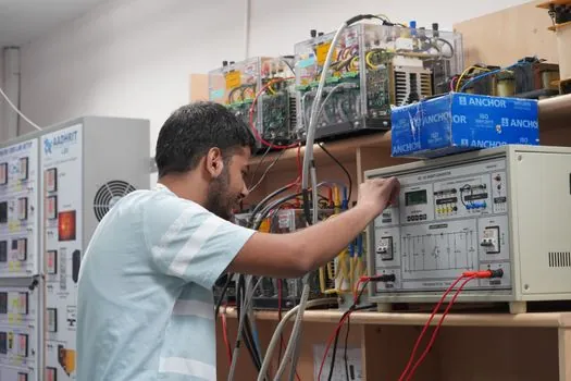
Microprocessor protection is suitable for medium-voltage substations, distribution feeders, power transformers, generators, motors, transmission lines, renewable-energy systems, and industrial power systems [S2]. It is a strong fit where several coordinated functions, disturbance records, remote access, and low CT burden are required in a compact panel footprint [S1][S2][S4].
It is less suitable when a simple, single-function device is all the process requires, when the owner will not maintain settings and test records, or when obsolete communication and firmware support would undermine the expected lifecycle benefit [S1]. Replacement of an electromechanical relay should also account for the forced-outage cost of the failure, since that consequence can exceed the physical cost of the protection equipment [S1].
For motor-focused installations, the CT accuracy and burden decision needs specific treatment rather than reliance on a generic microprocessor label. The motor protection relay CT accuracy class guide provides a focused comparison for the CT side of that selection. On the relay itself, verify actual function availability, measurable setting ranges, sampling performance, communication compatibility, and IEC or IEEE compliance required by the project [S2].
The strongest procurement file separates four layers: relay technology, protection function, operating characteristic, and lifecycle support. The next trackable signal is the approved settings and commissioning schedule, followed by factory and site test evidence for pickup, timing, direction, trip outputs, records, alarms, and communications.