Three principal stepper motor constructions, variable reluctance, permanent magnet, and hybrid, differ in rotor architecture, step resolution, torque behavior, and practical application [S3][S4].
A two-phase bipolar motor uses 2 coil groups and typically 4 leads, while a four-phase unipolar motor uses 4 coil groups; both winding arrangements can be implemented in permanent-magnet or hybrid machines [S2].
Construction Classes: VR, PM, and Hybrid
Variable-reluctance, permanent-magnet, and hybrid are the three established construction classes of stepper motor [S4][S6]. A variable-reluctance motor combines a wound stator with a soft-iron, multitoothed rotor that moves toward energized stator poles, producing no permanent rotor magnet [S4]. Permanent magnet stepper motors are particularly suitable for applications requiring high load and low speed, such as printers, plotters, woodworking machines, and industrial robots [S5].
A permanent-magnet motor uses a magnetized rotor with alternating north and south poles parallel to the shaft.
Hybrid synchronous motors combine permanent-magnet and variable-reluctance construction features. Their finer angular resolution, stronger holding torque, and broader operating envelope make them the common choice for 3D printers, precision positioning, and industrial automation [S3][S5]. Hybrid construction does not itself specify whether the windings are unipolar or bipolar, so motor architecture and drive topology must be considered separately [S2][S5].
Unipolar and Bipolar Winding Classifications
A two-phase bipolar stepper has 2 groups of coils and generally exposes 4 wires, with 2 conductors assigned to each phase [S2]. The driver reverses current through a phase to move the magnetic field in the opposite direction, allowing both winding poles to participate in torque production [S5].
A four-phase unipolar stepper has 4 coil groups, and each phase commonly includes 4 windings or connection points in a common-center arrangement [S2]. This topology simplifies driver current direction because each phase is energized from one side of a center tap. The simpler commutation arrangement suits compact automation and small robots, but it does not use the full two-pole magnetic capability of a comparable bipolar winding [S5].
The explicit comparison is straightforward: bipolar winding offers more efficient use of the phase magnetic field and is established in precision equipment such as 3D printers and CNC machines; unipolar wiring simplifies driver implementation; hybrid construction generally adds torque and resolution rather than defining winding polarity [S3][S5]. A useful control reference for these alternatives is the stepper drive.
Step Count, Resolution, and Speed Limits
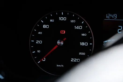
A 1.8° motor is equivalent to a 200-step-per-revolution motor because 360° divided by 200 produces the 1.8° nominal step angle [S2].
The number of stator poles and rotor teeth determines the step angle and resolution of the stepper motor [S3].
This creates a selection trade-off rather than a universal performance ranking. High-resolution machines suit slow, accurately positioned axes, while low-step-count machines can favor speed and torque. Microstepping further subdivides each commanded step for smoother motion, lower acoustic noise, and reduced vibration, but that subdivision is a drive operating technique rather than a separate motor construction class [S3][S5].
Frame Size and Torque Qualification
Stepper frames range from units smaller than a peanut to NEMA 57 machines, with NEMA 17 commonly used in 3D printers and smaller CNC mills [S2]. Larger NEMA frames are associated with CNC machines and industrial equipment because greater frame size generally permits greater power output, although the frame designation itself does not guarantee identical electrical or mechanical performance [S2].
NEMA numbers define mounting faceplate dimensions rather than torque, step angle, current, or accuracy. Two NEMA 17 motors can therefore differ materially and remain non-interchangeable unless their mechanical and electrical ratings match [S2]. The catalogue entry for each candidate should be checked for rated torque, operating current, voltage, inductance, step angle, and required driver supply before frame size is accepted as sufficient evidence.
Where Each Type Fits
Permanent-magnet motors fit cost-sensitive, low-resolution positions where a typical 7.5° to 15° step and 24 to 48 steps per revolution are acceptable [S4]. Typical uses include printers, plotters, woodworking machines, and industrial robots where low-speed torque and load handling matter more than fine angular resolution [S5].
Variable-reluctance motors fit applications that prioritize efficient operation, dynamic response, and higher speed, including industrial automation, collaborative robotics, and CNC machinery [S5]. Hybrid motors fit the broad industrial middle ground, combining high holding torque, finer resolution, and operating versatility for applications such as 3D printing, robotics, CNC positioning, and industrial automation [S3][S5].
This class is not appropriate where continuous high-speed operation, very high shaft power density, or a heavily damped dynamic load dominates the duty cycle. Stepper motors can resonate if poorly controlled, and operating near or above 3000 rpm is identified as difficult [S4]. For applications requiring verified position under variable load, disturbance, or lost-step conditions, closed-loop control can verify and correct discrepancies between commanded and actual positions [S5].
Geared, Shaft, and Feedback Options
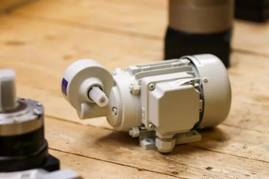
A 32:1 gear train applied to an 8-step-per-revolution motor produces 256 output steps per revolution while increasing output torque [S2]. The same reduction reduces speed and introduces gear backlash, which must be taken up during direction reversal and can affect positioning accuracy [S2]. Geared steppers are therefore suited mainly to low-speed actuator duties where torque multiplication outweighs the speed and backlash penalties.
Shaft construction must match the mechanical interface. Round and D shafts support conventional pulleys, gears, and couplers, with the D-shaft flat resisting slippage under torque [S2]. Geared shafts mate with modular trains, while lead-screw shafts convert rotary motion into linear movement and are used in miniature disk-drive head positioners and related actuators [S2].
Integrated electromechanical designs can reduce assembly work by placing drive electronics, encoder feedback, and fieldbus communication within the motor package. The associated hardware choices are covered in integrated stepper motor configurations. A servo motor is the more suitable alternative when closed-loop dynamic control and high-speed performance are more important than simple pulse-and-direction positioning.
Specification Checklist for Procurement
A complete procurement record should specify construction, winding arrangement, phase count, nominal step angle, rated current, voltage, holding torque, frame size, shaft configuration, insulation requirements, and the intended pulse frequency [S2][S4]. Frame, phase, and step-angle labels alone are insufficient because NEMA size does not define electrical performance, and a 2-phase bipolar motor has different coil and lead requirements from a 4-phase unipolar motor [S2].
Drive selection must match the winding topology and voltage and current ratings, while the application duty must be checked against the motor's torque-speed behavior. Full-step, half-step, and microstepping modes change motion smoothness and effective resolution, while pulse frequency sets commanded speed [S3][S4]. Closed-loop feedback should be added when load disturbance or guaranteed position cannot be verified from command pulses alone [S5].
The next verifiable engineering check is to compare the required peak and running torque at the actual commanded speed against each candidate's torque-speed curve, then confirm that the pulse rate, drive current, frame dimensions, shaft interface, and any required feedback match the machine specification [S2][S4].