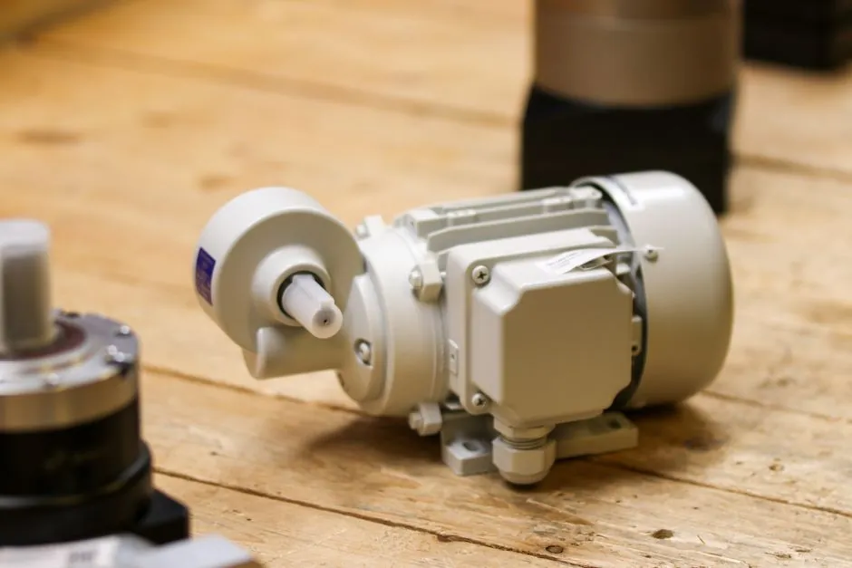
A correctly sized motor protection relay starts with the motor nameplate current, then confirms that the adjustment range, trip class, CT input, and protection functions match the actual starting duty.
This guide applies to low-voltage and medium-voltage motors, thermal overload relays, and microprocessor protection relays used in pumps, compressors, fans, conveyors, and other rotating equipment.
Start with motor nameplate data
The nameplate full-load current is the primary overload setting reference, not motor horsepower, contactor continuous-current rating, drive output current, or a generic table value. The nameplate records the current associated with the motor's actual winding design, rated voltage, frequency, and load [S5].
A 15 kW, 400 V, three-phase induction motor can have a nameplate FLC of 28 A even though a generic table may show 29–30 A for a related frame. If the relay adjustment band is 23–32 A, 28 A sits comfortably within that range; the same example would be poorly conditioned if the chosen band ended at 28 A [S5].
Record at least six nameplate fields: rated voltage, rated current, frequency, number of poles, starting method or duty, and service factor. A service factor of 1.15, where present, describes the motor's additional thermal capacity and does not replace FLC as the base overload setting [S5]. ABB also cautions that protection values may vary with motor manufacturer and pole count, so generic values are guidance rather than a substitute for project data [S1].
Match relay range, frame, and contactor
The relay's adjustable current range must bracket the nameplate FLC, and its physical frame must fit the specified contactor. Common bimetallic ranges are arranged around values such as 9–13 A and 23–32 A, a 1:1.5 span, while Siemens SIRIUS 3RU21 products are divided among S00, S0, S2, and S3 frames [S5].
Electrical compatibility is only one constraint. A relay can cover the required current while still failing to mount on the installed contactor, and a manually reset device can impose a different operating workflow from an auto-reset unit. Schneider TeSys LRD ranges extend from about 0.10 A to 630 A, while ABB TA families include TA25DU, TA200DU, and higher ranges designed for matching contactor families [S5].
For a new panel, the shortlist should therefore contain the relay range, frame or contactor family, trip class, reset mode, auxiliary contacts, and manufacturer coordination-table reference. For a retrofit, the installed contactor model must be confirmed before ordering. The motor protection relay reference explains how the protective device fits into the wider motor-control arrangement.
Use trip class to match starting behavior
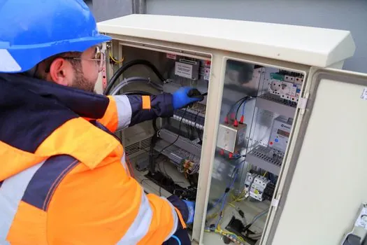
Trip class is the time-delay class that controls how quickly an overload relay responds to excess current. Classes 10, 20, and 30 designate increasing response delays, with Class 10 generally used for IEC applications and Class 20 common among NEMA-rated relays; an unmarked relay is treated as Class 20 [S3].
Selection should follow measured starting behavior. Direct-on-line starts impose the greatest initial current demand, while star-delta, soft-starter, and VFD applications reduce or reshape inrush. The relay must allow the motor to accelerate without nuisance trip, but it must still interrupt a sustained overload [S4] [S5].
The practical decision sequence is: nameplate FLC, relay range, contactor frame, then trip class. Setting the relay to FLC does not validate the selected class. A high-inertia or long-acceleration load can require a slower class than a short-cycle machine, while an application with rapid acceleration may operate successfully with a faster class [S5]. The separate analysis of Class 10 versus Class 20 versus Class 30 relays provides a useful response-time comparison.
Compare thermal and microprocessor options
Thermal overload relays protect a motor by heating a bimetal element from motor current and opening an auxiliary contact that de-energizes the contactor coil. Microprocessor relays instead determine protection from measured current and, where fitted, temperature inputs, protection functions, event data, and communications [S3] [S4].
A thermal relay is appropriate when direct-on-line motor control needs dependable overload protection with simple local operation. Its limitations include ambient-temperature effects, limited information retention, and less flexibility when several coordinated functions or remote diagnostics are required. Electronic overload relays suit variable-frequency drives and applications needing selectable characteristics, start inhibit, phase monitoring, or communications [S2] [S5].
For a microcomputer protection platform, current rating alone is an inadequate comparison. Use four criteria: current range and accuracy, trip-class or protection timing, input and output functions, and monitoring architecture. A local thermal relay may win on simplicity, while a microprocessor relay wins where a digital power monitoring system or remote diagnostics is required.
Size CT inputs for MV motor protection

Medium-voltage motor protection normally requires current transformers because the relay input accepts a standardized measurement signal rather than the motor's line current directly. The CT ratio must be chosen from motor FLC, the relay's secondary current input, and the required measuring range, with CT accuracy and burden checked against the relay specification [S4].
A motor protection relay with a 1 A or 5 A secondary input is not automatically compatible with every CT ratio. The CT ratio, accuracy class, secondary rating, and burden must form a complete chain with the relay, including margin for the motor's starting and operating currents [S4].
For tender schedules, include the motor FLC, CT ratio, CT accuracy designation, CT secondary rating, relay input rating, and conductor or cable information. Detailed CT selection is covered in Motor Protection Relay CT Accuracy Class: 5P, 10P, PX.
Choose protection functions by load
Overload, phase-loss, phase-unbalance, locked-rotor, and ground-fault functions address different motor failures, so one relay should not be treated as interchangeable with another merely because both carry the nominal FLC. The protection function list should be derived from motor rating, load, starting method, installation environment, and coordination requirements [S4].
Pump and fan motors usually need overload protection plus phase monitoring, with trip timing matched to the inertia and process start. Compressors can impose repeated starts, high breakaway torque, or rapid cycling. Conveyors may require starting inhibition and undercurrent or load monitoring to detect a failed belt or jammed drive [S4].
Two operating rules prevent common errors. First, the overload relay is not a substitute for short-circuit protection. Second, opening an overload relay contact does not guarantee that all hazardous electrical energy has been removed; isolation and lockout remain separate safety requirements. The overload contact typically controls the contactor coil rather than interrupting the motor's main fault current [S3].
Apply a staged selection workflow

Use an 8-stage workflow for a repeatable specification: collect nameplate data, confirm voltage and current range, define required protection functions, assess the starting method, characterize the load, verify CT compatibility, establish relay settings and coordination, and document communications and monitoring needs [S4].
For an IEC thermal overload relay, the final setting is normally the nameplate FLC, subject to the manufacturer's specified adjustment range and application guidance. IEC 60947-4-1 covers overload relays for motor protection, and the research identifies Classes 10A, 10, 20, and 30 as relevant trip classes [S5]. NEMA-style relay adjustment bands are often narrower than IEC ranges: the published guidance describes typical adjustment of about ±15% around the normal trip current for NEMA devices, compared with an adjustment capability commonly up to 50% above normal trip current for IEC devices [S3].
Do not use the mainstream adjustable thermal relay as the default for every motor. It is a poor fit for a VFD application that needs electronic overload modeling, for an MV installation requiring CT-based measurement, or for a process that requires event history and remote alarms. Select a microprocessor relay when the functional or diagnostic requirement exceeds a local thermal device.
The shortlist logic is straightforward: choose the trip class that tolerates the measured start, select the range and frame that accept nameplate FLC, add CT inputs for MV measurement, and retain only functions supported by the motor and process risk assessment. Before approval, verify the relay model, adjustment band, contactor frame, reset mode, trip class, CT ratio, auxiliary contacts, communication protocol, and manufacturer coordination table against the approved motor data sheet [S4] [S5].