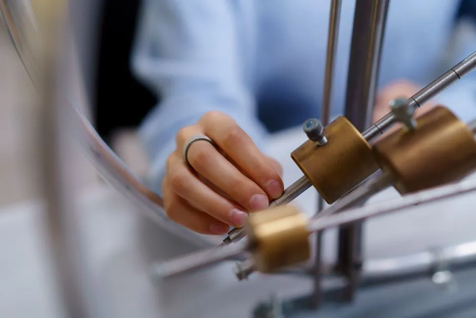
Most O-ring failures are born on the assembly bench, not in service. Damage during installation (spiraling, tearing, and overstretching) accounts for the majority of early-life seal failures documented in industry guidance [S3].
The mechanics that drive those failures are well understood: undersize rings tear, oversize rings fail to seat, rolling the ring into the groove causes spiral failure with characteristic 45 degree surface cuts, and petroleum-based lubricants can swell or dry out NBR, EPDM, and FKM depending on formulation [S3][S4]. A disciplined install sequence (verify size, slide, mask threads, lubricate with a compatible fluid) eliminates the bulk of those problems.
Acceptance Criteria: Sizing, Stretch, and Gland Fill Before You Press
O-rings are dimensionally specific to their groove; an undersized ring is prone to breakage and tears during assembly, while an oversized ring will not adequately seal against fluids or gas at operating pressure [S3]. The practical stretch ceiling is 50% of the ultimate elongation of the O-ring compound, and the less you stretch the ring, the tighter the finished seal will fit [S2][S3].
On the gland side, good practice holds groove fill under 100%, with Parker's recommended radial lead-in chamfer at 15 to 20 degrees and an opening that exceeds the maximum installed height of the O-ring in the groove [S4]. For a quick field check, Pi-tape and tapered measuring cones give a reading without removing the part, which is faster and more repeatable than calipers on a soft elastomer. For material context that drives compound choice upstream of installation, the O-ring type and classification reference covers the standard families.
Sliding vs Rolling: Why the 45 Degree Cut Happens
Rolling an O-ring into its groove causes spiraling, and spiral failure surfaces as the ring being caught on an eccentric component or against a cylinder wall, producing twisting and 45 degree angle cuts on the seal surface [S3]. The corrective action is mechanical, not chemical: slide the ring into place over the shaft or into the bore so the cross-section seats uniformly.
This is the single highest-leverage habit change on the bench. Apple Rubber's published guidance states outright that O-rings should always be slid into place, not rolled, and that a well-lubricated ring makes that slide a non-event for the operator [S3]. For static face-seal and dovetail grooves, the same rule applies: lead the ring in flat, never tumble it along the groove wall.
Sharp Edges, Threads, and the Hidden Tear Problem
Mating gland components frequently carry sharp edges or threads that the seal must pass over during installation, and those features can produce tears so small they are invisible to the naked eye but still produce a leaky seal at first pressure test [S3][S4]. The masking-tape workaround is the lowest-cost field fix: cover male threads with a couple of turns of tape so the ring cannot catch a thread crest.
If tape is not available, a compatible grease or high-viscosity silicone oil on the thread zone achieves the same protective film. Either way, the inspection loop matters: any ring that was forced past a suspect edge should be scrapped, not reused, because damage installed at the bench will not heal at pressure. Related reading on static seal hardware and flange install checks sits in flange gasket installation: procedure, failure modes, and acceptance checks.
Lubricant Selection by Compound and Service Temperature
Lubrication reduces surface friction between the O-ring and mating surfaces, allowing the ring to seat in the groove with very little effort, and in male/female radial seals it cuts the installation force and smooths piston insertion [S4]. The matching rule is non-negotiable: lubricant must be compatible with the seal elastomer, suitable for the application temperature, compatible with the system fluid, capable of high surface tension, and must not clog system filters [S4].
Concrete published choices: Parker O-Lube is a general-purpose grease for hydrocarbon service with a recommended service temperature of -20 to 180 degrees F (-29 to 82 degrees C), while Super-O-Lube is a high-viscosity silicone oil rated -65 to 400 degrees F (-54 to 204 degrees C) for broader thermal range [S4]. Avoid soap-and-water for anything that will see re-wetting in service, and avoid petroleum jelly on EPDM or silicone if the system fluid specification calls for those families [S3]. A side-by-side reading of lubricant versus material sits in the O-ring encyclopedia entry.
Decision Table: Installation Method by Failure Mode

The four-row table below maps the most common installation failure modes to the action that prevents them, the acceptance check, and the point at which you should replace rather than rework the part. [S3]
Symptom 1: spiral failure with 45 degree surface cuts. Root cause: ring rolled into the groove. Corrective action: slide ring into place, lubricate the groove and ring. Acceptance: cross-section seats flat, no twist visible. Replace, do not rework, if the cut is deeper than a surface scratch [S3].
Symptom 2: neck-down tear at the stretch zone. Root cause: stretch exceeded 50% of compound ultimate elongation, often on a shaft fit. Corrective action: re-select a smaller cross-section or a larger shaft diameter, and verify with Pi-tape. Acceptance: installed stretch measured under 50%. Replace any ring that necked during fit-up [S2][S3].
Symptom 3: leak at first pressure test with no visible damage. Root cause: micro-tear from a thread crest or sharp edge. Corrective action: mask threads, chamfer lead-in to 15-20 degrees, re-lubricate. Acceptance: hold test pressure for the specified dwell. If the ring was dragged over a suspect edge, scrap it [S3][S4].
Symptom 4: swelled or shrunken ring after install. Root cause: lubricant incompatible with elastomer (petroleum on EPDM, for example). Corrective action: change to a lubricant matched to both compound and system fluid, and re-cut the groove dimensions if the swell altered the gland fill. Acceptance: groove fill stays under 100% at installed state [S3][S4].
When to Stop and Re-spec Instead of Re-installing
If the same lot of rings keeps failing on the same gland, the answer is not a better installer, it is a re-spec. Groove fill above 100%, lead-in chamfer below 15 degrees, or a service temperature outside the lubricant's published range are design-level issues that an installation procedure cannot fix [S4].
Trackable signals to watch: a first-test leak rate above the equipment acceptance threshold, repeat spiral-failure cuts on the same line, or any swell/shrink greater than the elastomer compound's published tolerance band. Each is a stop-the-line event, not a tweak the operator should paper over. For static seal hardware adjacent to this work, the gasket trade-off reference covers when to switch from an O-ring to a flat gasket entirely.
Closing note: the next signal worth tracking is the move toward temporary rubber assembly lubricants (P-80 style emulsions) for dry-fit assemblies where residue must evaporate after install, especially in medical and food-grade lines [S1]. Also watch for updated Parker O-Ring Handbook revisions on groove fill tolerance, since that document is the field reference most shops cite when an installation dispute lands on a QA desk [S4].
Spec-level background on the components involved: linear guide, and crossed roller guide.