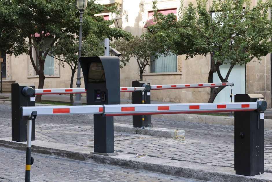
Regulatory Guide 5.44 (USNRC, Revision 1) sets the original performance criteria for perimeter intrusion alarm systems protecting nuclear-fuel facilities: detect the presence of an individual or vehicle in the isolation zone, localise the alarm to a uniquely identified segment, and remain operable under controlled functional testing [S1]. CLC TS 50661-1:2017 layers a parallel European framework — system requirements for external perimeter security systems — that any EU industrial site tender will reference [S8]. Treat both as the design baseline; vendor marketing sits on top, not in place, of these documents.
Stage 1 — Site Survey and Perimeter Classification
Regulatory Guide 5.44 requires the isolation zone surrounding the physical barrier to be monitored, and explicitly states that the choice of perimeter alarm system is influenced by considerations of terrain and climate, with no single sensor type capable of operating effectively in all environments [S1]. That sentence is the single most important survey deliverable: produce a written matrix mapping each perimeter segment against terrain (flat, undulating, fenced wall, water-facing, vegetation-dense), climate (rainfall, snow, fog, temperature swing, salt-air exposure), and threat (casual trespass, organised intrusion, vehicle ramming).
CLC TS 50661-1 formalises the same idea as a system-requirements document: external perimeter security systems must perform under declared environmental and operational conditions, with performance verified at the segment level rather than as a whole-loop metric [S8]. A segment-by-segment survey feeds directly into the segmentation strategy in Stage 3 and the sensor-mix decision in Stage 2. Skipping this step is the single most common root cause of perimeter alarms that detect reliably for six months and then drift into chronic nuisance once seasons change.
Stage 2 — Technology Selection Across Six Sensing Families
Modern perimeter alarm installations draw on six established detection families, and the installed system is almost always a hybrid of two or more of them [S2]. They are: active infrared beams (transmitter-receiver pair interrupted by an intruder), microwave/RF barriers (volumetric detection between two units), fibre-optic sensing (cable laid on the fence or buried detects strain/vibration), radar/electromagnetic wave systems (Doppler or FMCW detection across an open zone), microphonic cable (acoustic signature analysis along a fence), and piezoelectric or pressure-sensitive buried lines (intruder footfall weight on a buried transducer).
The two leading physical-security OEMs in this market segment — GPS Standard, an Italian manufacturer with over 50 years of perimeter-security experience [S2], and Allied Fire & Safety Equipment, a New Jersey-based integrator installing microprocessor-based infrared, microwave, audio and sensor-driven detection since the 1970s [S3] — both build their product lines around the same six families. The selection rule is straightforward: pair a fence-following sensor (fibre-optic, microphonic cable) with a free-standing volumetric sensor (microwave, radar) so the system catches both fence-cutting/climbing and walk-through-the-gap events, and add active infrared at gates and doorways where the perimeter is broken for legitimate traffic.
Stage 3 — Segmenting, Power, and Signal Infrastructure
Regulatory Guide 5.44 specifies that the perimeter should be divided into segments that are independently alarmed and uniquely monitored, so the security response can localise the alarm to the segment of origin and so a portion of the system can be tested or maintained while the remainder of the perimeter stays under monitoring [S1]. A practical design rule: each segment should be short enough that a single responder standing at one end of the segment can visually observe the entire segment — typically 50-100 m for a fence line, shorter for a wall.
Power and signal infrastructure is the failure mode that gets neglected in budget reviews. A perimeter alarm segment needs supervised power (battery-backed, with monitoring for brown-out and cut), supervised signal line (line-fault detection end-to-end), and a signal path that survives a single cable cut — typically a loop topology rather than a radial. For an installation tied into a building management or PSIM stack, the segment controllers should expose dry-contact or IP outputs per segment; the integration software layer is then the place where intrusion detection, video surveillance, access control, and fire detection are correlated [S2]. The cost of getting this stage wrong is paid for the next 15 years in false alarms, not at handover.
Stage 4 — Mounting, Alignment, and Environmental Hardening
Active infrared and microwave barriers require precise alignment at install — typically within ±0.5° of the optical/RF axis — and their mounting posts need a rigid foundation that does not move with frost heave or wind loading. The NRC guide notes that many systems rely on self-excitation of the sensor transducer (vibration, strain, pressure) while others monitor the signal level at the receiving transducer (microwave, infrared), and that the self-checking feature varies by type and design [S1].
For outdoor work, IP65 or higher enclosures are the minimum; for coastal or chemical atmospheres, expect to specify 316L stainless hardware and IP66/IP67 enclosures. The fence itself is part of the sensor: a sagging fence causes fibre-optic and microphonic systems to false on wind, and an over-stretched fence reduces sensitivity. Tighten the fence before you calibrate the sensor, not after. See the parallel guidance on mounting and acceptance discipline covered in planetary reducer alignment and acceptance — the same alignment-then-torque-then-test sequence applies to perimeter sensor mounting.
Stage 5 — Commissioning and Functional Performance Testing
Two distinct test regimes apply, and conflating them is a common commissioning error. Operability testing — a guard or watchman penetrating the zone during a routine patrol to confirm the segment alarms — is the daily-life check. Functional performance testing is the formal commissioning gate, performed under controlled circumstances with direct visual observation of the area being tested, and is what proves the system meets the declared detection probability and false-alarm rate [S1]. CLC TS 50661-1 expects the same controlled-condition testing as the basis for system-level acceptance [S8].
Reject any segment whose measured false-alarm rate exceeds the design target, or whose response time exceeds the security-response time budget. This is also the gate at which the perimeter alarm is tied into a fire alarm control panel or a gas alarm controller where the site safety case requires it — a perimeter event may need to trigger HVAC isolation, fire damper closure, or emergency ventilation, and that integration is commissioned here, not later.
Stage 6 — Handover Documentation and Sustained Operability
To ensure normal operation, the system may periodically monitor the sensor transducer and signal-processing circuits, and a self-checking feature can be built in depending on type and design [S1]. That self-check is only as good as the test it runs; insist on a documented self-test schedule and a written procedure for the controlled-condition functional retest at defined intervals (typically quarterly, with a full annual re-baseline).
Hand over an as-built segment map, every sensor's serial number and measured coverage footprint, the segment-level detection and false-alarm data from commissioning, the loop topology drawings, and a maintenance schedule keyed to the linear guide discipline of scheduled replacement of wear parts (battery packs typically 3-5 years, IR source degradation 7-10 years, fibre-optic cable 15+ years if mechanically protected). For a multi-vendor integration stack, the access control systems trade-off map and the perimeter alarm types classification map are useful references when aligning the perimeter alarm with adjacent subsystems.
Track two signals over the first 12 months of operation: segment-level false-alarm rate per 24 hours (rising trend = environmental drift, equipment degradation, or vegetation growth into the detection field) and mean time to repair per segment (rising trend = spares, training, or documentation gaps). Either trend is a credible leading indicator that the installation is sliding out of its design window, and both are addressable without replacing the system — but only if the per-segment baseline from Stage 5 is on file.