
Concrete pavement grooving should target the specified depth within a common 3.2–6.4 mm range while preserving the required width and blade spacing [S3][S4].
Define the groove depth before operating the cutter
Groove depth is a measured construction parameter, not an operator preference. Historical California highway grooving used groove widths and depths ranging from 1/8 to 1/4 inch and longitudinal grooves spaced from 3/8 to 1 inch center to center [S3]. Historical California highway patterns covered the same 1/8–1/4 inch depth range, with groove widths of 1/8–1/4 inch and cut spacing of 3/8–1 inch center to center [S3].
Grooving requirements for pavement safety marking materials shall conform to the details shown on work orders or plans and as directed by the Engineer [S2].
Those values serve different applications. A 3.2 mm groove is a transverse pavement groove, while a recessed-marking cut also creates space for the applied marking material. Equipment selection should therefore follow the project specification rather than a universal depth number.
Compare depth-control methods for pavement grooving
This requirement favors an independently adjustable head over an uncontrolled fixed-position setup, especially where the cutter has separate depth and width adjustments.
A concrete groove cutter should therefore be evaluated by three criteria: positive depth adjustment, free-floating response, and the ability to hold the planned width and spacing [S1][S2].
Calibrate cutting-head height against the target groove
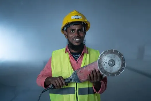
Start with a short trial section on the pavement and measure the finished groove with an appropriate depth gauge. Compare the result with the project limit, such as 1/8–1/4 inch for pavement grooving or 30–40 mils plus marking thickness for recessed markings [S2][S4].
Do not judge depth from the cutter's position alone. A head that appears correctly set can still produce a shallow or deep groove if the machine bridges a hollow, operates against a grade, or uses worn diamond tooling. The operating reference should be the finished pavement surface, not an unloaded bench setting.
Match cutter tooling to the required groove profile
Concrete grooving machines can use multi-pointed flails, TCT cutters, or diamond blades to form lines and channels [S5]. Concrete grooving machines may use multi-pointed flails, TCT cutters, or diamond blades to rotate and groove lines on concrete surfaces [S5].
Depth control cannot correct an unsuitable profile. The selected tooling must produce the planned groove shape while leaving the finished surface free of ridges.
Blade width also affects the finished geometry. The historical California examples combined a 1/8 inch width with a 1/8 inch depth, while the full documented range reached 1/4 inch for both dimensions [S3]. If the project calls for equal width and depth, confirm the actual blade and head assembly rather than relying on a machine's general grooving description.
Use separate controls for depth, width, and spacing
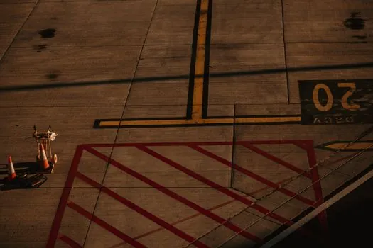
Depth adjustment, groove width, and longitudinal spacing are separate acceptance variables. An operator who changes blade position to solve one parameter can alter another, so each setting needs verification against the approved drawings or work order [S1][S2].
The depth device is responsible for maintaining the vertical cut dimension, while blade spacing determines the transverse pattern.
For a comparison with another cutting-control problem, circular saw depth at 90 degrees versus 45 degrees illustrates why a single machine depth setting does not define the finished geometry. Pavement grooving is governed by the cut profile in the finished surface, not by the angle or nominal position of the cutter alone.
Inspect the finished groove under traffic and surface conditions
Acceptance checks should cover both groove geometry and the condition of the finished pavement. The New York specification requires the pavement to remain undamaged and prohibits a pattern that could mislead or misdirect motorists [S2].
Measure representative grooves at intervals established by the project specification. Record depth, width, spacing, surface condition, and the location of each test. Check transitions, joints, repaired areas, and visibly uneven pavement because these are the locations most likely to expose a weak depth-control response.
Traffic-control and staging requirements remain part of the operation. Work performed under traffic requires flags, markers, signs, and other devices to protect the work area, while an approved operations schedule is required before grooving begins [S2].
Prevent depth drift from setup and wear
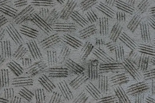
Depth control should be verified before production, after tooling changes, and whenever the cutter moves between pavement sections. The machine must first be set to the target geometry, then tested over the surface conditions it will cut, rather than assuming a successful setup on one slab will transfer unchanged to the next [S1][S2].
Three practical controls reduce depth variation. First, confirm that the depth device physically changes cutting-head height. Second, verify that the head is free-floating where required. Third, compare measured grooves with the acceptance range, here 1/8–1/4 inch for the cited pavement-grooving applications [S1][S2][S4].
For wet operation, flush each groove immediately with high-pressure water and allow the surface to dry before applying recessed marking material. For dry operation, use vacuum recovery during grinding and remove remaining debris before the surface is accepted [S2].
The next trackable signal is not a machine display reading. It is the measured depth of finished grooves across the trial area, recorded against the approved range and checked again after diamond dressing, tooling replacement, and changes in pavement profile.