
Sensor selection begins with the maximum average running torque and then accounts for probable peak torque, starting conditions, and other application requirements.
Correct sizing also requires probable peak torque, overload capacity greater than twice the calculated probable peak torque, starting conditions, maximum rotational speed, allowable error, and mechanical compatibility with the shaft.
Convert shaft power into rated torque
Use P = T × ω, with ω expressed in radians per second. In practical motor calculations, the equivalent form is T (N·m) = 9550 × P (kW) / n (rpm) [S4].
For a 5.5 kW motor at 1,440 rpm, the result is approximately 36.5 N·m. At the same power, reducing speed to 720 rpm doubles the torque to approximately 73.0 N·m, which explains why speed must be part of the rating calculation [S4].
For a torque-limited driveline rather than a motor-nameplate case, use the mechanical power reaching the measured shaft. The sensor rating must cover that operating point, not merely the motor’s maximum catalog output. A power meter can provide the electrical or mechanical power needed for this calculation, while shaft speed remains a separate measurement unless the sensor includes integrated speed sensing [S3].
Account for service and probable peak torque
Rotary machinery generally produces pulsating rather than perfectly smooth torque, so the selection procedure starts with maximum average running torque and then applies load and drive service factors [S2].
The published method defines probable peak torque as PPT = MART × (LSF + DSF), where MART is maximum average running torque, LSF is load service factor, and DSF is drive service factor [S2]. The calculation uses the lowest speed at which maximum rated power is developed, which produces a conservatively sized sensor when speed varies with load [S2].
Set the overload capacity for shocks and starting
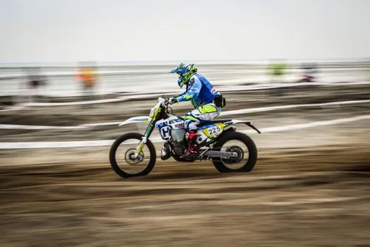
This overload requirement is separate from the normal measurement range and from the maximum speed rating.
Starting conditions must be accounted for when sizing a rotary torque sensor.
The distinction matters because a sensor can have sufficient steady-load capacity yet fail during startup. A motor producing 36.5 N·m continuously is not fully characterized by that number alone.
Compare installation types against shaft constraints
An inline torque sensor is appropriate when the driveline can be modified or disassembled, while bolt-on cells, surface-mounted telemetry, and electrical power meters support measurements on installed shafts without that work [S3]. The selection then shifts toward installation geometry, shaft diameter, and sensor construction.
Check speed, mechanical loading, and accuracy
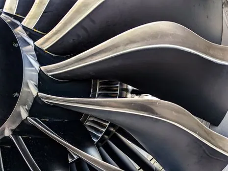
Speed rating is a separate constraint from torque capacity because rotational speed changes the dynamic environment and the centrifugal load generated by rotating components.
Accuracy must be stated as an allowable measurement error and checked against the required test resolution [S2]. The selection should also account for electrical noise and electromagnetic interference, since incorrect shielding, grounding, or signal conditioning can degrade the measurement even when the mechanical capacity is adequate [S2].
Measurement duration affects the instrumentation architecture. If power measurement is required, speed measurement can be added, either as an integrated feature or as a separate speed sensor.
Confirm the final selection against service conditions
The defensible sizing sequence is: calculate rated torque from power and speed, determine MART at the lowest relevant speed, apply LSF and DSF, calculate PPT, confirm overload rating above 2 × PPT, check starting torque, verify speed and extraneous-load ratings, and then confirm accuracy [S2].
For an example using only the published factors, a 5.5 kW motor at 1,440 rpm gives 36.5 N·m. With LSF = 2 for a conveyor and DSF = 0 for a smooth three-phase AC motor drive, PPT = 36.5 × 2 = 73.0 N·m, and the overload rating must exceed 146.0 N·m [S2][S4]. A variable-frequency drive changes the DSF treatment and therefore changes the final result [S2].
Keep the final purchase specification tied to operating speed, measured shaft power, load class, drive type, shaft dimensions, installation loads, and accuracy requirement. This prevents a sensor selected only from nominal torque from being undersized for peaks or mechanically incompatible with the driveline.