
For clean liquids in the 0.8 to 2 centistokes viscosity band, a turbine flow meter holds linearity within plus or minus 0.5% of reading across a 10:1 turndown and stays repeatable to plus or minus 0.1% over 20:1 to 100:1 [S3]. Sizing the meter so the minimum expected flow stays inside that linear window is the difference between a custody-transfer-grade reading and a number you have to qualify with a viscosity correction.
This article walks through how to pick a meter line size from minimum and nominal flow, what "linear range" actually means on a manufacturer's data sheet, where the K-factor starts to bend, and how viscosity, straight-pipe runs, and pick-off electronics change the practical floor. Reference points include Hoffer inline turbine guidance, the Webtec LT-range linearisation work, and the mid-range sizing rules published by DwyerOmega and Turbines Incorporated [S1][S2][S3][S5].
What "Minimum Linear Flow" Means on the Data Sheet
Manufacturers publish two distinct floors: a linear flow range and a repeatable (extended) flow range. For Hoffer inline liquid turbines calibrated in the 0.8 to 2 cstks band, linearity is typically plus or minus 0.5% of reading across a 10:1 turndown, while repeatability of plus or minus 0.1% is held across 20:1, and can stretch to 100:1 depending on the coil and bearing combination [S3]. Below the published linear floor the K-factor starts to drift because bearing friction and viscous drag no longer scale linearly with flow; the meter still pulses, but the pulses-per-unit-volume value quoted on the calibration certificate no longer applies without correction [S3][S5].
The standard webtec linearisation study is built on exactly this point: across a 5:1 flow range the K-factor stays within plus or minus 0.25%, but the curve flattens sharply as flow approaches the meter's lower threshold, and a different oil viscosity or temperature will move that knee [S5]. Treat the data-sheet "minimum linear flow" as the lowest GPM (or L/min) at which the published K-factor is valid without linearisation math; treat "minimum repeatable flow" as the floor for trending and totalising, not for billing.
Pick the Line Size from Nominal, Not from Pipe Diameter
The mid-range sizing rule is consistent across vendors: anchor the normal operating point inside roughly 30% to 70% of the meter's rated capacity, with the tighter 60% to 75% band preferred when the process is steady [S1][S2]. Picking by line size alone is the most common field error; an oversized meter on a low-velocity line leaves the rotor below its linear floor, while an undersized meter raises velocity and pressure drop to the point where backpressure can damage bearings [S1].
A working method: (1) identify the minimum, nominal, and maximum (peak) flow rates of the system, noting that the maximum must include any short surges; (2) overlay these against the candidate meter size's published linear flow range; (3) confirm the nominal flow rate falls within the meter's linear operating range, where the meter will perform with highest accuracy and repeatability; (4) verify the maximum flow rate does not cause the meter to over-range or become damaged; and (5) confirm the minimum flow rate is above the level at which the meter can register and respond accurately [S1]. For the Webtec LT range, the T1, T2, and T3 sizes cover 4 to 125, 15 to 400, and 25 to 800 L/min respectively, which gives a concrete reference for matching nominal to size [S5].
How Viscosity and Bearing Drag Shift the Linear Floor

Turbine meters are calibrated on a fluid of a specific viscosity at a specific temperature, and the K-factor only holds for that combination [S3][S5]. Above about 2 cstks, viscous drag starts to dominate the torque balance on the rotor; bearing friction, magnetic detent, and fluid drag all add together, and the K-factor curve bends earlier and at a higher flow [S3][S5]. Hoffer's own guidance is to use only the linear flow range when the process fluid is more viscous than the 0.8 to 2 cstks calibration band, and to apply a transmitter or flow computer with linearisation if the application forces operation into the repeatable-but-non-linear region [S3].
Practical signals that viscosity is moving your minimum linear floor: K-factor drift between calibration bath and process fluid, output that drops to roughly 20 mV peak-to-peak at the low end of the pick-up coil's range, and rotor slow-down visible on a portable frequency counter at the expected minimum GPM [S2][S4]. The 20 mV figure is the reluctance-pickup warning level cited by DwyerOmega, below which signal conditioning or a preamplifier becomes mandatory if the meter-to-electronics distance is more than a short cable run [S2].
Pickup, K-Factor, and Why the Low-Flow Pulse Is the Weak Link
Every blade pass generates one pulse; the K-factor, expressed in pulses per gallon or pulses per litre, is the bridge between frequency and flow [S2][S3][S4]. For a reluctance pick-up the coil is a permanent magnet and the blades are ferromagnetic; pulse amplitude at low flow can drop to around 20 mV peak-to-peak, and that signal must not be run more than a short distance before preamplification [S2]. Hall-effect sensors switch on the order of 25 gauss and produce a cleaner square wave, but they still need minimum blade velocity to trigger reliably, which sets a hard floor below the published linear range [S2].
At low flow the practical sizing check is whether the resulting pulse frequency is high enough for the receiving instrument. With a 3 pulses per gallon K-factor, 1 GPM yields only 3 Hz, which is right at the edge of what many flow computers resolve cleanly [S4]. If the calculated minimum frequency is below about 10 Hz, the meter is almost certainly operating below its data-sheet linear floor, and the sizing decision needs to step down to a smaller line size to push velocity (and pulse rate) back into the linear window.
Straight-Pipe Runs, Swirl, and What Breaks the Calibration
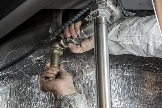
Turbine meters measure average velocity across a symmetrical profile, so anything that distorts the profile bends the K-factor at the low end first. Hoffer's installation rule is 10 diameters of straight pipe upstream and 5 diameters downstream of the meter, using the nominal turbine inlet size as the reference [S3]. Below the linear floor the rotor is most sensitive to swirl, because the few blade passes per second are easily skewed by residual rotation from an upstream elbow or a partially closed valve [S3][S5].
Webtec's LT-range meters ship with two six-arm flow straighteners, one upstream and one downstream of the rotor, specifically to flatten the profile before the blade tip sees it [S5]. The check on a real installation is to put a portable frequency counter on the pick-up with the process at minimum flow: if the indicated frequency is unstable or drops out at the expected minimum GPM, the straight-pipe geometry is almost always the culprit, not the meter itself.
Sizing Rules Compared: Where the Numbers Agree and Diverge
Two rules-of-thumb for nominal flow placement and one for turndown show up across the sources. Turbines Incorporated places nominal flow at roughly 30% to 70% of rated capacity for best accuracy and repeatability [S1]. DwyerOmega tightens that to 60% to 75% of maximum for the most stable K-factor region [S2]. Webtec reports plus or minus 0.25% K-factor stability over a 5:1 flow range on its LT series [S5].
The combined decision matrix: (1) placement of nominal flow (30% to 70% looser, 60% to 75% tighter); (2) linear turndown available (10:1 typical for Hoffer, 5:1 for the Webtec LT series on the strict K-factor definition); (3) repeatable turndown available (20:1 to 100:1 depending on coil and bearing); (4) viscosity band for which the K-factor is valid (0.8 to 2 cstks for Hoffer inline liquid calibration) [S1][S2][S3][S5]. If minimum flow would push the meter below the 10:1 linear floor, either step down one line size, restrict operation to the linear range only with a linearising transmitter, or pick a different measurement principle such as a Coriolis flow meter for high-turndown viscous service.
Working Sizing Procedure, From Flow List to Verified K-Factor

Step 1: collect minimum, nominal, and peak flow for the process, plus fluid viscosity at operating temperature and any expected viscosity swing [S3]. Step 2: pick a candidate meter line size whose published linear range brackets minimum and whose rated maximum exceeds peak; confirm nominal lands between 30% and 70% (or 60% to 75% for the tighter rule) of maximum [S1][S2]. Step 3: confirm the calculated pulse frequency at minimum flow is high enough for the receiving electronics, remembering that 3 pulses per gallon at 1 GPM is only 3 Hz [S4]. Step 4: check straight-pipe geometry against the 10D upstream / 5D downstream rule, or verify the meter has internal flow straighteners like the Webtec LT series [S3][S5]. Step 5: for viscous service above 2 cstks, restrict operation to the linear range and apply linearisation in the flow computer, or revisit the meter choice [S3].
If the process minimum flow keeps forcing operation in the repeatable-but-non-linear band, an electromagnetic flow meter is worth evaluating for conductive clean liquids where very low minimum velocity is required, or a vortex flow meter for steam and gas services where the minimum linear flow constraint is tied to a different Reynolds-number window. For custody-transfer-grade hydrocarbon or chemical service where turndown matters more than clean-flow constraints, a Coriolis flow meter typically replaces a turbine at the sizing stage rather than being paired with one.
Failure Modes at the Low-Flow End
Three failure modes show up repeatedly in field reports: rotor stall below minimum linear flow producing a constant zero or a stuck low reading; K-factor drift when the process fluid viscosity differs from the calibration bath, which the Webtec study shows can shift the linearisation curve substantially across the full 5:1 range [S5]; and signal loss in long cable runs from a 20 mV peak-to-peak reluctance pick-up, which forces a preamplifier or a switch to a Hall-effect sensor [S2].
The 25-gauss trigger threshold for Hall-effect sensors is a useful diagnostic number: if a magnet brought near the rotor blade tip does not switch the sensor output, the pick-up itself is suspect, not the meter's linear range [S2]. The plus or minus 0.5% linearity spec from Hoffer is also worth quoting to a customer as a contractual figure, because that is the spec the K-factor is warranted against; everything outside the 10:1 turndown is repeatable but not linear without compensation [S3].
Track these on a sizing sheet for the next review: (1) the candidate meter's published linear floor in the operating-viscosity band; (2) the calculated pulse frequency at minimum flow against the receiving instrument's input spec; (3) the straight-pipe run in front of the meter against the 10D upstream rule. If any of those three lines does not close, sizing has to iterate before a purchase order is cut.
See also our earlier report, Standard AGV Load Capacity for Unit-Load Pallet Transport.