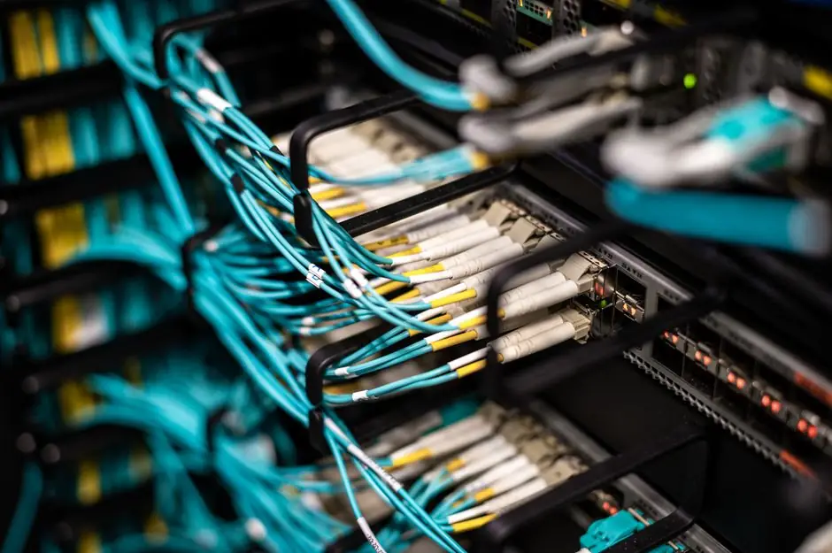
On a Synchronous Serial Interface (SSI) link, the master sets the clock and the encoder shifts out position bits synchronously; the faster the clock, the shorter the cable you can run before the edges smear and the receiver mis-clocks the data [S3]. SICK's interface document puts the hard ceiling at 1.5 MHz for synchronous SSI over cable, and 2 MHz baud in general, with the actual usable rate chosen against the installed cable length [S3].
Engineers in the field see a clean trade: roughly 400 m at 125-250 kHz, around 50 m or less near 1 MHz, and a few kilometres only if you drop to RS-485-style low-bit-rate regimes (10 kbit/s over about 1 km) [S2][S9]. The physical layer is RS-422/EIA-422 differential signalling on a twisted, shielded pair, which is what lets SSI stretch past SPI's 1 m ceiling while still needing careful clock budgeting [S4][S5].
Why Clock Rate Sets the Cable Ceiling
SSI's data line is sampled on the encoder's clock edges; any round-trip delay longer than a fraction of the bit period pushes the latched data into the next bit window and corrupts the frame [S3]. Cable capacitance, not DC resistance, is usually the first constraint that bites, which is why the same 24 AWG twisted pair works fine at 100 kHz for hundreds of metres and falls apart at 2 MHz over even 10 m [S3][S4].
Differential RS-422 transmission gives SSI a wide common-mode range and high noise immunity, which is why it survives plant environments at all; even so, the bit period has to exceed cable propagation delay plus encoder monoflop/transfer-time, and that envelope shrinks linearly with clock rate [S4][S7]. A controller running 2.5 MHz on an RMC200 S8 module, for example, only works on short pigtails, while the same module at 100 kHz can be used on much longer runs [S1].
Clock Rate vs Cable Length: A Practical Comparison
The table below lines up the four decision criteria that matter on the shop floor: clock frequency, maximum cable, transmission type, and typical use case. Numbers come from the cited OEM and integrator sources, not from generic marketing copy. [S3]
Delta Motion's SSI fundamentals chart maps 100 kHz to 2100 ft (640 m) and 150 kHz to 1360 ft (415 m) on RS-422 [S1]. Sick's encoder datasheet confirms 1.5 MHz as the cable-limited synchronous ceiling and 2 MHz as a baud upper bound [S3]. TWK's system description picks 300 kHz specifically as the maximum permitted clock for 200 m of cable, which gives a clean working point for long-run multiturn feedback [S8]. Scancon's 2RK SSI datasheet exposes the device-side capability at 100 kHz to 2 MHz, showing where the encoder itself stops being the bottleneck [S10]. EVRTP's SSI primer summarises the RS-422 case at up to 1200 m (4000 ft) when the clock is tuned down to match [S4]. Industrial Monitor Direct's May 2026 integrator write-up lands in the same window: 400 m at 125-250 kHz, 50 m or less at 1 MHz [S2].
For a 25-bit multiturn, the slower end of this chart is usually fine, since one full frame at 100 kHz still completes in about 3 ms; for a 32-bit multiturn at high servo rates, designers push the clock up and trim the cable accordingly [S1][S3].
Who SSI Is For, and Where It Stops Making Sense
SSI fits single-axis or small-cluster high-precision feedback where you want absolute position without a reference run, including rotary encoders on servos, linear encoders on machine tools, and magnetostrictive displacement transducers to 1 µm or even 0.1 µm resolution [S1][S4]. The point-to-point nature of the interface is a feature in motion control: each encoder has its own clock and data pair, the master latches the position on the first falling edge, and a transfer-timeout of 20 µs minimum enforces frame integrity [S3][S4].
SSI is the wrong choice when you need many devices on one bus, when cable runs exceed about 1200 m, or when you need hot-swap multi-drop addressing; for those, RS-485 protocols (up to 64 addressable nodes on a single bus) or Ethernet-based fieldbuses take over [S5]. It is also the wrong choice when you need the highest single-axis speed with long cable, since the same application can be served by an absolute encoder protocol comparison where the cable-length budget is matched to the bit rate up front, rather than fought at commissioning [S9].
Selection Criteria Engineers Actually Use
Three numbers decide the design: clock frequency, cable length, and required update rate. The standard design choice is RS-422 differential on twisted shielded pair, four conductors total (Clock+, Clock-, Data+, Data-), with the encoder latching position on the first high-low clock edge and shifting MSB-first on subsequent rising edges [S3][S4]. SICK specifies this electrical layer explicitly, including the recommendation for twisted-pair signal lines and differential evaluation to cut EMC sensitivity [S3].
The link budget is then set by choosing the lowest clock that still meets the control loop's update-rate target. For a 25-bit frame, 200 kHz gives a frame time of about 1.25 ms including the 20 µs monoflop, which is plenty for most servo loops; 1 MHz drops that to 250 µs but cuts the usable cable to roughly 50 m on typical encoder cable [S3][S8]. When the application is dominated by long cable rather than high bandwidth, the displacement transducer accuracy comparison framing in the spec literature is a useful reference, since magnetostrictive SSI devices share the same RS-422 cable physics and use the same clock-vs-length envelope [S1][S4].
Failure Modes and Common Pitfalls

Three things break SSI links in the field: running a high clock into a long cable, mixing single-ended and differential devices on the same controller, and ignoring the monoflop/transfer timeout. RMC SSI inputs, for example, require RS-422 5 V differential and explicitly do not support single-ended SSI or higher-voltage inputs, so a single-ended encoder on a long cable will not work even at a conservative clock [S1].
Clock-rate mismatch shows up as bit errors near the LSB, intermittent all-zeros or all-ones error patterns (the standard SSI error flags), or complete frame loss when cable propagation exceeds the bit period [S1][S3]. Cable capacitance on un-twisted or un-shielded runs is the usual culprit on long links, not DC resistance, which is why OEM guidance is to use twisted-pair cable that complies with RS-422 and to keep the clock at or below the rate the cable can support [S3][S4].
Standards, Sourcing, and What to Specify
Physically, SSI sits on EIA-422 (RS-422) or EIA-485 (RS-485), with RS-422 differential signalling being the usual choice for absolute encoders because of its common-mode range and noise immunity [S3][S4]. Clock and data are differential pairs, twisted and shielded, with the master setting timing and the slave returning MSB-first data, and no multi-drop addressing in the standard design [S3][S5]. The clock ceiling for synchronous SSI on cable is 1.5 MHz; for general baud it is 2 MHz; and the same differential layer supports clocks from 100 kHz to 10 MHz only on very short, controlled-impedance links [S3][S7].
When you spec a cable for an absolute encoder on SSI, three values fix the design: target clock in kHz, required cable length in metres, and frame size in bits. Match the clock to the cable against the published envelope, and verify that the controller supports the same RS-422 electrical layer and the same monoflop/transfer-timeout window as the encoder. For long-cable or low-bandwidth applications, the limit switch box and limit switch product categories face the same RS-422 cable-budget discipline, even though the protocol is different, so the same engineering checklist applies. For absolute position over linear encoder feedback at moderate cable lengths, 100-250 kHz is the standard working point and gets you 400-1200 m without exotic cable [S2][S4].
Trackable signals to watch: vendor datasheets publishing explicit clock-vs-length tables rather than generic 1200 m claims, controller modules exposing configurable clock rates down to 100 kHz (RMC200 S8 and U14 already do, down to 100 kHz with seven discrete steps to 2.5 MHz) [S1], and the slow shift toward 10 MHz-capable short-cable variants for high-speed servos where cable length is engineered to be short [S7].