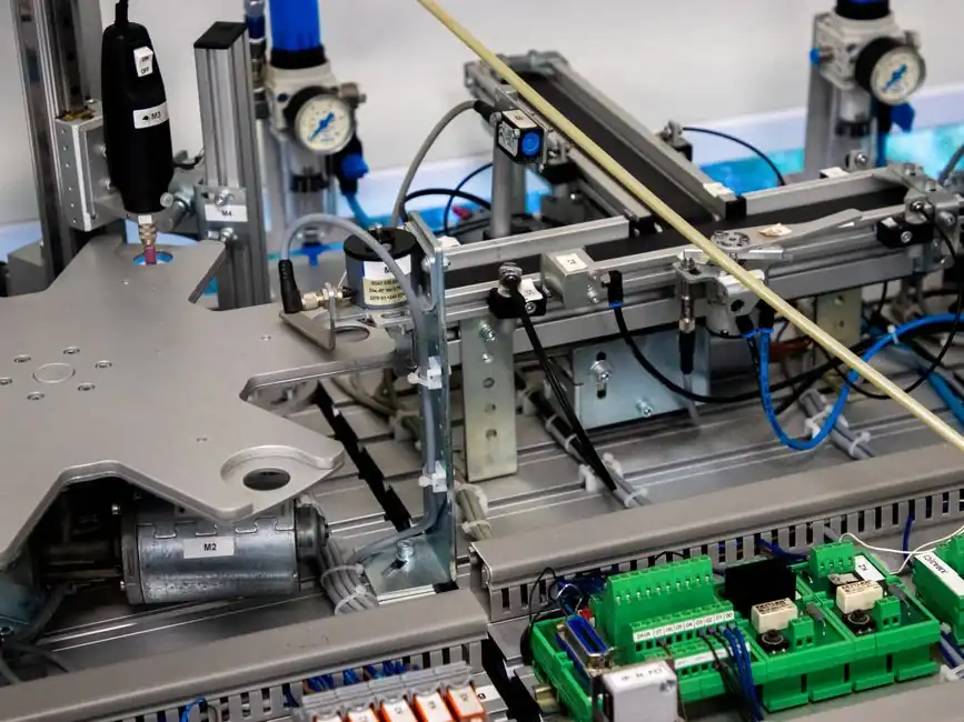
A stepper motor holds position because the rotor sits magnetically locked to the stator field at its last commanded step, not because any sensor confirms where the shaft is [S1]. The drive issues a fixed number of step pulses; the rotor advances one full step angle per pulse (typically 1.8° on a 200-step/rev hybrid stepper, or finer with microstepping) and stops in the last energised phase, where detent torque plus the holding current through the windings resist external disturbance [S5].
The catch is that this holding force is open loop. There is no encoder, no resolver, and no index pulse returning to the controller, so the drive cannot distinguish "rotor at commanded position" from "rotor stalled 4 steps ago" [S1][S3]. For low-speed, steady-load applications, that is acceptable; for any axis where a missed step is a scrapped part, an encoder or homing reference is mandatory.
Why an Open-Loop Stepper "Holds" at All
The holding torque is the maximum static torque the motor can resist while energised at rated current, with no rotation. In a 2-phase hybrid stepper, that torque comes from the alignment of the rotor's permanent-magnet field with the stator's synthesised field at the last microstep, plus the reluctance contribution from the tooth geometry [S5]. With phase current held, the rotor resists displacement up to a limit set by the load.
There is also a small residual "detent" torque when the windings are unpowered, produced purely by the permanent magnet seeking the lowest-reluctance tooth alignment, typically only a few percent of rated holding torque and not strong enough for most production holding requirements. Real-world holding needs full rated current through the windings, which means continuous I²R losses and waste heat even when the axis is stationary [S1][S5].
Because the drive has no way to verify rotor angle, stepper sizing rules specify a torque margin: common practice is to size the motor 1.5 to 2 times larger than the load strictly requires, with operation held 30 to 50% below the published pull-out torque at the worst-case speed [S1]. That margin absorbs the dynamic loads the system cannot measure.
The Silent Failure Mode: Loss of Synchronism
The defining failure of an open-loop stepper is loss of synchronism, formalised as "step loss" or "loss of synchronism" per NEMA ICS 16-2001 [S1]. When instantaneous load torque exceeds the motor's pull-out torque at the current speed, the rotor falls behind the rotating stator field by one or more electrical steps. The drive keeps issuing pulses as if nothing happened, and every subsequent move is offset by the lost steps [S1][S3].
Position error under load is proportional to the load, dominated by friction at steady speed and by inertia during acceleration and deceleration. With dynamic loading, belt stretch, bearing wear, and aging can shift the operating point over months, and the open-loop drive cannot flag the change [S3]. A CNC cuts the rest of the part at an offset, a 3D printer produces a layer shift, and neither the controller nor the operator gets a warning until the part is already wrong [S1].
Step loss is also a problem at standstill if the load can back-drive the rotor. A visitor pushing a smart-blind drivetrain manually, or a vertical axis losing power, displaces the rotor past the holding torque limit; the drive has no record of the move and resumes the wrong position the next time it pulses [S2].
What "Closed Loop" Actually Means on a Stepper

There are at least three different control schemes sold under the "closed-loop stepper" label, and they are not equivalent [S1]. Specifying on the marketing term alone is a known source of integration problems.
The sizing impact is large. With continuous position feedback, the 30 to 50% torque margin below pull-out is no longer required, so the motor can be selected 1.5 to 2 sizes smaller for the same load; closed-loop steppers also run cooler, quieter, and with lower vibration than open-loop units, because current is matched to actual load rather than held at full rated current at all times [S1][S4].
Encoder Options When You Do Close the Loop
Incremental encoders give relative position and need a homing routine to find absolute zero on power-up; they cannot tell the controller whether the shaft was moved while the system was off [S2][S4]. Absolute encoders (optical or magnetic multi-turn types) provide a unique position value for every shaft angle, so no homing is required and the position is known immediately after power-on or after an unexpected move [S2][S4].
Common stepper-integrated resolutions are 1,000, 2,500, 5,000, or 10,000 counts per revolution (cpr), giving 0.36° to 0.036° electrical resolution; combined with a 200-step/rev motor, even 1,000 cpr is 5× finer than a full step, and 10,000 cpr is 50× finer [S4][S5]. For a stepper motor holding a load with closed-loop verification, the relevant spec is not just the cpr but the encoder's commutation accuracy, the closed-loop bandwidth of the drive, and whether the drive runs a true position loop or only a stall-detection flag.
For applications where the load must be measured at the mechanism rather than at the motor shaft, an external linear encoder on the slides or a rotary encoder on the gear reducer output closes the loop at the point where position actually matters, which removes the effects of lead-screw pitch error, belt stretch, and gearbox backlash from the position budget. Selection criteria and the trade-offs between contact and non-contact displacement sensing are covered in contact vs non-contact displacement sensors and in displacement transducer accuracy by technology class.
Decision Matrix: Open Loop vs Encoder-Equipped vs Servo

The choice is driven by speed, torque, and what failure of the axis costs. Below 1,000 rpm, a stepper delivers higher torque density than a comparable-frame brushless servo, and that is the speed band where a closed-loop stepper is most often the right answer [S1].
Open loop is for low-cost, low-speed, low-inertia axes with conservative sizing and a homing switch on power-up, for example 3D printers, small index tables, and consumer appliances, where a missed step is recoverable or non-critical [S3][S5]. Closed-loop stepper (incremental encoder, FOC) is for CNC axes, packaging, medical fluid handling, and semiconductor handling, where missed steps are not acceptable but the cost of a true brushless servo is not justified, and where the operating speed stays below roughly 1,000 rpm [S1][S4]. Sensorless back-EMF schemes fit only well-behaved, constant-load, mid-speed applications where occasional missed steps are tolerable [S3][S6]. A true brushless servo with rotary encoder feedback and high-bandwidth FOC is for high-speed spindles, high-dynamic-response axes, and any application where the stepper's low-speed torque advantage is irrelevant above 1,000 rpm [S1][S3].
Failure Modes, Limitations, and Sourcing
Open-loop steppers fail silently: lost steps accumulate, the part is wrong, and the only recovery is a homing cycle and operator inspection [S1][S3]. Closed-loop steppers using incremental encoders fail in a different mode, they forget absolute position on power loss and need a homing routine on every restart, unless paired with an absolute encoder or a battery-backed multi-turn unit [S2][S4]. Sensorless steppers fail when the operating point drifts outside the back-EMF detection envelope (too slow, too lightly loaded, or load too dynamic), giving false negatives on stall detection [S3][S6].
For sourcing, hybrid steppers with integrated optical or magnetic encoders are stocked by several Chinese manufacturers in 28, 35, 42, 57, 86, and 110 mm frame sizes, typically with 1,000 to 10,000 cpr encoders, optional gearboxes, brakes, and matched stepper drive electronics; suppliers also sell NEMA 17/23/34 closed-loop "integrated servo stepper" modules with the encoder, drive, and connector loom in one housing [S4]. Verifying the exact closed-loop scheme (move-and-verify vs sensorless vs FOC) on the drive datasheet is a hard requirement; the marketing term "closed loop" does not guarantee the same control architecture across vendors [S1].
Watch the drive datasheet for the actual control-loop structure, the encoder resolution and protocol (TTL quadrature, SSI, BiSS, or absolute single-turn), the rated continuous current versus peak current, the protection set (over-current, over-voltage, over-temperature, position-following-error), and the cable specification for the encoder harness in moving installations. For position verification at the load rather than at the motor, spec a linear encoder on the slides, and budget its resolution against the stepper motor step angle and the stepper drive microstep setting so the position loop is not oversampled or undersampled. Related reading on selection trade-offs in motion control: hydraulic motor displacement vs torque and speed.