Vision measuring machines deliver non-contact 2D/2.5D dimensional data on machined, stamped, and semiconductor features, with typical optical magnification ranges such as 100–500X on auto-focus systems [S8]. Surface roughness testers, by contrast, resolve micro-vertical deviations on a part surface and express them as parameters derived from a roughness curve, a role that has no substitute in any 2D imaging chain [S7].
Both instrument families sit next to each other in every Indian and Chinese metrology catalog — profile projectors, vision measuring machines, contour instruments, and roughness testers are routinely listed by the same supplier [S4]. The vendor base is broad: a single made-in-China index alone shows 621 roughness-measuring manufacturers supplying 1,863 distinct product lines, with median entry-level price points around US$ 343 per set [S9].
What each instrument actually measures
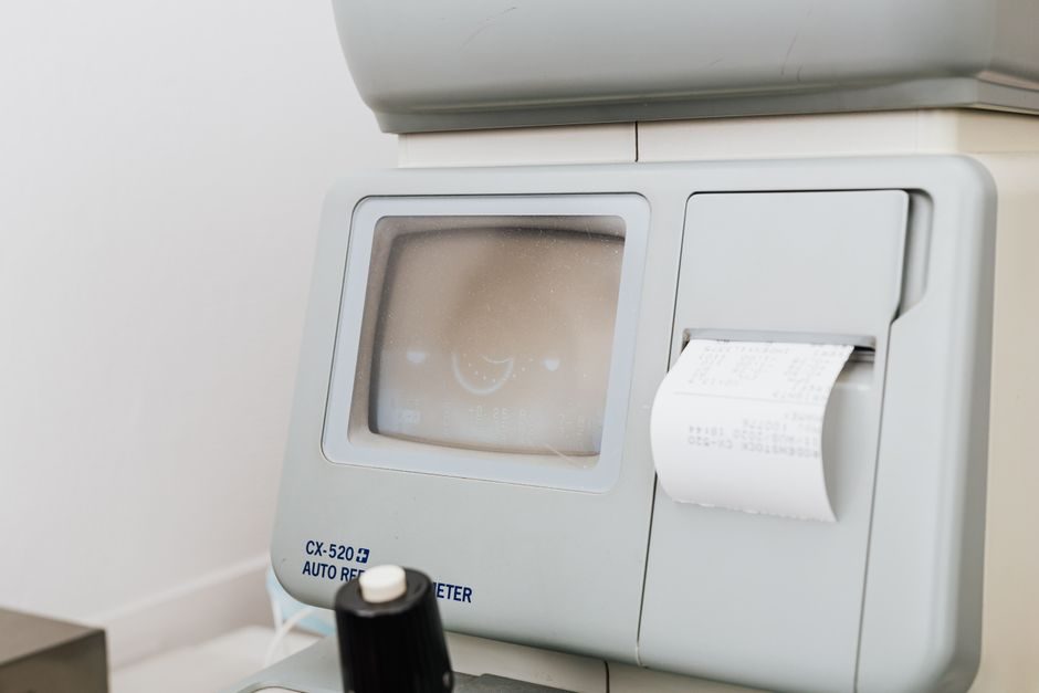
A VMM images a part under a calibrated zoom lens and uses edge-detection software to compute lengths, angles, hole positions, and GD&T callouts such as position and concentricity; semiconductor-grade 2.5D auto-focus VMMs are specifically built to image small features with stable focus across the field of view [S8]. The output is dimensional — units of length and angle — not surface texture.
A surface roughness tester resolves the micro-vertical profile of a part, and contact designs use a diamond stylus that physically traces the surface while non-contact designs use a laser or optical probe on the same evaluation area [S7]. The output is a roughness parameter such as Ra, Rz, or Rq, derived from a filtered roughness curve, and the result drives machining-process tuning rather than dimensional acceptance [S2].
Where vision systems step into the roughness domain
Machine-vision-based roughness assessment is a documented research field, not a marketing line: a 2023 Springer study developed a system using curvelet and contourlet transforms on imaged surfaces to grade roughness, framing it as a way to remove the human error tied to tactile stylus work [S1]. An earlier 2016 study on FDM-printed parts compared a light-sectioning vision method directly against a conventional stylus, demonstrating that the optical path can return usable roughness values on non-metal additively manufactured surfaces (2016-08) [S10].
The catch is scope: those vision-based roughness paths are surface-texture systems, not the same hardware sold as a VMM. Optical roughness instruments, whether they are confocal, focus-variation, or light-sectioning, share the camera and lighting stack of a VMM but add a vertical scan axis and ISO 21920 / ISO 25178 evaluation routines. Buying a vision measuring machine and expecting an Ra readout is a spec error that surfaces in almost every retrofit project.
Selection criteria: a four-row comparison
Engineers usually run the choice through four gates. First, the measurand: VMM answers "how big / where is the feature," surface roughness tester answers "how smooth is the surface." Second, the contact state: VMM is fully non-contact; surface roughness testers come in contact (stylus) and non-contact (laser/optical) variants, and the choice governs whether soft or delicate parts can be measured [S7]. Third, the parameter on the drawing: 2D distances, angles, hole-to-hole tolerances go to VMM; Ra / Rz / Rq in the surface-finish callout go to a roughness tester. Fourth, the production environment: portable handheld stylus units are common on shop floors, while benchtop VMMs and benchtop profilometers are typical in metrology rooms [S3].
For production-line coverage, surface roughness testers are "widely used in production site to measure surface roughness of various machinery-processed parts," and the parameter is computed and displayed by the instrument itself [S3]. A VMM is the wrong tool for that work — even when the same supplier lists both product lines on the same catalog page [S4].
Who each instrument is for, and who it is not for
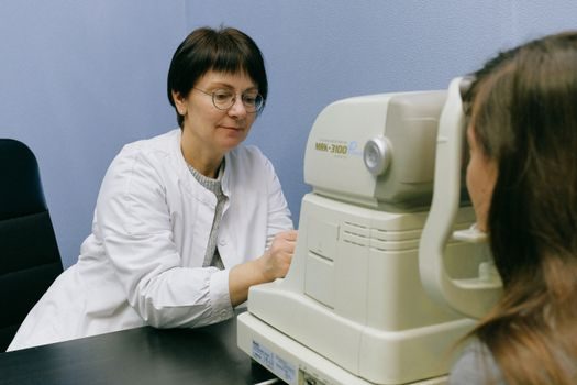
VMM is built for QA labs and inline cells that need fast, non-contact dimensional checks on small-to-medium prismatic parts, PCB features, or semiconductor packages, with magnification stacks reaching 100–500X on auto-focus heads [S8]. It is not built for sealing-surface finish verification, bearing-race Ra verification, or any callout that requires an Ra value on a drawing.
A surface roughness tester is built for any machined, ground, turned, milled, or additively manufactured surface where the surface-finish symbol appears on the print, and where a tactile stylus or focused optical probe can reach the evaluation length [S2][S7]. It is not built for feature-to-feature dimensional checks, even though vendors in the metrology channel (see machine vision system suppliers) commonly list both lines together [S4]. If the deliverable is an Ra value, the roughness tester wins; if the deliverable is a GD&T dimension, the VMM wins.
Limitations and failure modes in practice
Stylus roughness testers carry a maintenance liability: the probe tip radius and tip wear govern the filter response, and a worn tip has to be re-polished or replaced to keep the form stable [S7]. Optical non-contact roughness paths remove the tip-wear problem but trade it for sensitivity to surface reflectivity, coating color, and lighting geometry — the same sensitivity that an auto-focus VMM has to manage on shiny parts.
VMMs fail on rough, oily, or transparent surfaces because edge detection depends on a stable contrast transition; the same part measured on a VMM and then on a contour measuring machine can give different answers because the contour instrument traces a physical probe rather than inferring geometry from pixels. For a feature that is a roughness callout plus a dimensional callout in the same drawing zone, the practical answer is two instruments, not one.
Standards, sourcing, and pricing signals
Roughness evaluation follows ISO 21920 / ISO 25178 family rules, which define Ra, Rz, Rq and the filtering used to produce a roughness curve from the primary profile; VMM evaluations follow ISO 10360 length-measurement rules and the ASME Y14.5 / ISO 1101 GD&T framework. Surface roughness tester catalogs make the parameter lineage explicit: the result is a number, not an image, and the number is what the machinist uses to tune feeds and speeds [S2].
On the sourcing side, the 621-supplier index, 1,863 SKU count, and US$ 343 entry-level set are concrete market signals as of the May 2026 directory snapshot [S9]. Indian distributors such as QS Metrology and MISUMI India carry both VMM and roughness lines side by side, which is the easiest way for a buyer to compare quotation response time and calibration-traceability documents in one inbox [S4][S7]. The next trackable node is the calibration certificate: a stylus roughness tester needs a Ra reference specimen and the VMM needs a calibrated length standard, and the certificate stack is the easiest place to catch a mis-specified instrument before it lands on the shop floor.