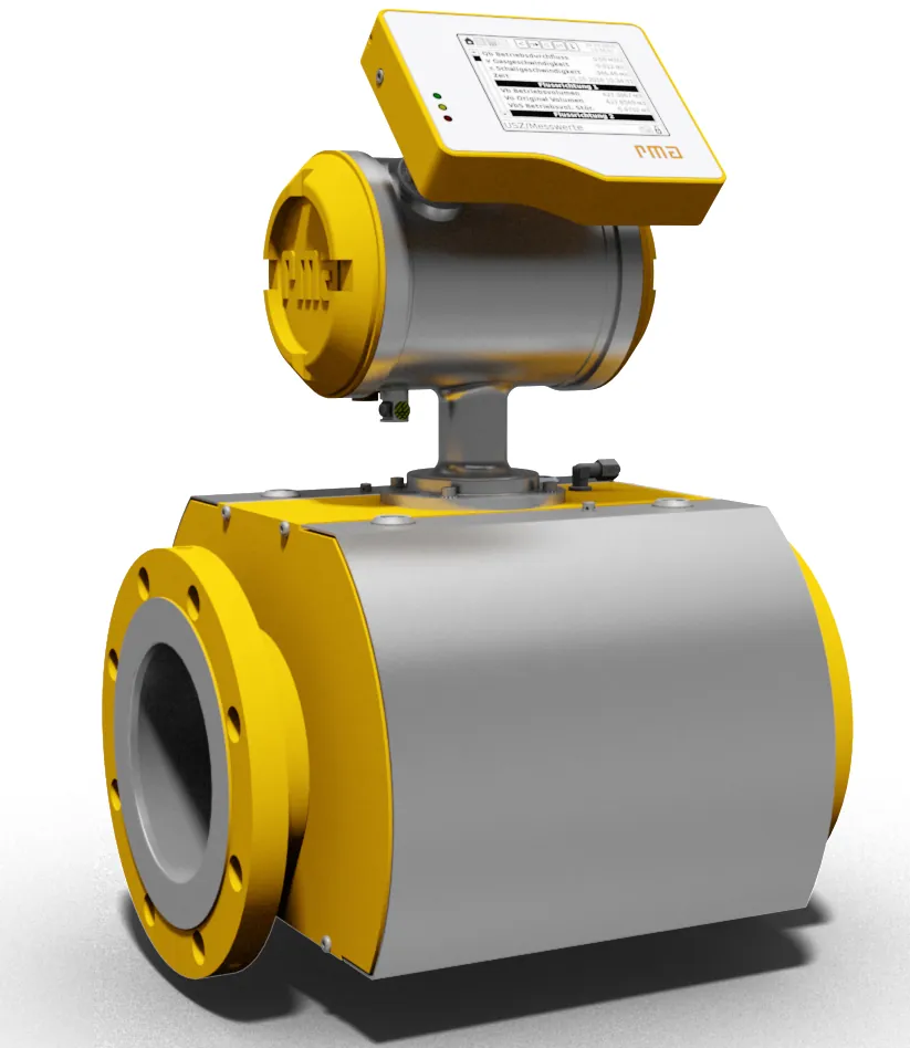
A clamp-on ultrasonic flow meter measures flow from outside the pipe: two piezoelectric transducers strap to the pipe wall, one upstream and one downstream, and the meter compares the transit time of ultrasonic pulses traveling with the flow against those traveling against it. The flowing liquid carries the with-flow pulse faster and delays the against-flow pulse, and the difference, after the meter's geometry model converts it through pipe diameter, wall thickness, and the liquid's speed of sound, is the average flow velocity along the acoustic path. Nothing enters the line: no pressure drop, no wetted parts, no process shutdown, which is why the form owns retrofit measurement, energy auditing, leak surveying, and temporary monitoring on lines that cannot be cut.
The specification problem is qualification, not sophistication. The meter is only as good as the pipe and liquid it looks through: wall material and thickness, liner condition, liquid sound speed and clarity, and the flow profile at the mounting point all decide whether the accuracy figure on the box survives installation. This page works the transit-time arithmetic and its Doppler sibling, the pipe-by-pipe qualification table, the V, Z, and W path configurations and when each applies, the honest accuracy expectations against ISO standards, and the RFQ lines that turn a site survey into a working meter rather than an expensive strap.
This page treats the clamp-on ultrasonic flow meter as a qualification exercise wrapped around a clean physics core: transit-time and Doppler measurement mechanics, pipe wall and fluid qualification tables, V Z W path geometry by size and condition, accuracy expectations against ISO 12242 and ISO 24062, the portable versus fixed and hybrid choices, and the RFQ lines that carry a site survey into a purchase.
Chapter 1 / 06
What a Clamp-on Meter Is and What Is Being Decided
The flow measurement market splits by how the instrument meets the liquid. Wetted technologies, an inline ultrasonic flowmeter with its spool piece, an electromagnetic flowmeter with its electrodes, a coriolis flowmeter weighing the fluid directly, a vortex flowmeter shedding into the stream, an orifice plate flowmeter taking a pressure drop, buy accuracy and permanence at the cost of cutting the pipe, stopping the process, and maintaining wetted elements. The clamp-on form buys the opposite: measurement through the wall, installed in an hour on a running line, moved to the next pipe the next day, at the cost of an accuracy class that depends on the installation's honesty. Neither is better; they are different tools, and the first selection decision is which one the duty is actually paying for.
What is being decided for a clamp-on unit is four qualifications and one configuration. First, the pipe: material, outside diameter, wall thickness, lining, and condition, because the acoustic model rides on all of them and a detached liner or a corroded wall quietly invalidates the model. Second, the liquid: sound speed at process temperature, clarity for transit-time work or particle and bubble content for Doppler, temperature range for the transducers, and whether the fluid is a liquid at all, since gases need transit-time designs of a different acoustic class. Third, the site: straight run upstream and downstream, access to a clean pipe surface, freedom from vibration and strong electrical noise, and space for the path geometry. Fourth, the performance expectation: whether the duty wants 1 percent class reading or survey-grade indication, which decides the care, and the price, of everything above. The configuration, single or dual path, V, Z, or W geometry, portable or fixed electronics, closes the purchase.
Positioning against the family is direct. A general ultrasonic flowmeter page covers the inline wetted designs whose calibrated spools hold better accuracy permanently; this page is the external cousin. A turbine flowmeter or variable area flowmeter serves clean low-volume lines with wetted mechanics; a thermal mass flowmeter serves gas mass duties; the clamp-on transit-time meter serves liquid volume, non-invasively, on lines from roughly DN13 to beyond DN6000 by maker. Where the line can be cut and the measurement is permanent and critical, wetted usually wins; where it cannot, or where the measurement is mobile, temporary, or auditing in nature, the clamp-on has no real competitor except the plant's belief that it can estimate flow from pump curves.
The honest summary of what the purchase buys: a flow signal proportional to the acoustic path velocity, corrected by the meter's model of your pipe and liquid, with an accuracy that the site either earns or spends. The instrument itself is mature, the physics is settled, and the vendors are many; what separates a good installation from a wasted one is entirely the qualification work described in the pages that follow. The rest of this page is about earning it.
Chapter 2 / 06
Transit Time and Doppler Physics
Transit-time measurement is a race. A pulse launched upstream-to-downstream rides the flow and arrives early; the same pulse launched downstream-to-upstream fights it and arrives late. The time difference is proportional to the average axial velocity of the liquid along the acoustic path, and the meter converts it to velocity through the path geometry, the pipe's inner diameter implied by measured outside diameter and wall thickness, and the liquid's sound speed. The conversion constants are why the site survey exists: enter a wrong wall thickness and the meter dutifully reports a wrong volume; enter a sound speed ten percent off, from a temperature guess, and the path geometry itself bends by that order. Modern meters walk the entry data through an acoustic model and flag inconsistencies, and the buyer's arithmetic is simply to treat entry data as calibration data, because that is what it is.
Doppler measurement is an echo. A continuous ultrasonic beam enters the liquid, scatters off suspended particles or bubbles, and returns shifted in frequency by the scatterers' velocity; the shift is proportional to that velocity. The requirements are the mirror of transit time: the liquid must carry reflectors, commonly slurries, sludges, aerated flows, and suspensions above roughly 0.2 to 2 percent by content depending on design, and the reading samples the velocity in the acoustic scattering region rather than a well-defined chord. Doppler accuracy class is therefore coarser, several percent and application-dependent, and its honest duty is indication and trending on reflective liquids where transit-time signal quality fails. Hybrid meters run both methods and let the electronics choose, which serves plants whose fluids change character by season.
Path geometry converts single chords into installations. The V path reflects off the opposite wall and returns to a transducer pair mounted on the same side, doubling the acoustic length and the timing leverage, the default for small and mid pipes. The Z path shoots directly across between transducers on opposite sides, shortening the path for large pipes, weak-signal liquids, and thick walls where every reflection costs amplitude. The W path bounces multiple times, stretching the path for very small pipes where a single traverse is too short to time well. Dual-path and multi-path clamp-on systems install two or more chord sets and average, cutting profile error and improving stability on large lines, and it is the multi-path configurations that push clamp-on accuracy toward the performance that wetted spools took for granted.
The flow profile is the physics that no strap-on can escape. A single acoustic chord samples a diagonal slice of the velocity distribution, and the meter applies a profile correction, Reynolds-number based in current instruments, that assumes the pipe's flow has developed its normal shape. That assumption is exactly why straight run exists in the specification: ten diameters upstream and five downstream is the common baseline, twenty and ten where the disturbance is a pump or partially open valve, and installations that cannot provide it accept profile error on top of the instrument's own class. Low velocity adds its own penalty, the profile flattens and the correction's assumptions soften, so the working band, roughly 0.1 to 12 meters per second on standard units with extensions at both ends, has an accuracy floor near the bottom.
Accuracy expectations, stated the way standards state them: a well-qualified single-path clamp-on on a clean metal pipe with good straight run holds roughly 1 to 2 percent of reading on liquids in its comfortable band, with repeatability a few tenths of a percent; multi-path installations tighten toward 1 percent and better; Doppler service carries several percent and the honesty to say so. ISO 12242 governs ultrasonic transit-time meters for liquids in closed conduits, and ISO 24062 addresses the clamp-on transit-time class specifically, both giving the buyer a vocabulary for what a vendor claims and under what conditions the claim was tested, which is the only way two datasheets can be compared at all.
Chapter 3 / 06
Pipes, Fluids, Configurations, and Boundaries
Instrument classes divide by electronics and by transducer family. Portable instruments, battery-powered or mains, with clamp rails and a logging brain, are the survey and audit tool: energy balancing, leak hunting, temporary monitoring, verification of other meters. Fixed instruments, DIN-rail or wall electronics with permanent 4 to 20 mA, pulse, and Modbus or BACnet outputs, are the permanent retrofit: a chilled water line that cannot be drained, a fire main, a heritage plant with no isolation. Transducer families divide by temperature class and acoustic frequency: standard units around minus 40 to plus 150 deg C by maker, high-temperature variants with waveguide couplings to roughly plus 200 deg C and beyond on steam-adjacent liquids, and frequency choices trading penetration for resolution, lower frequencies for large pipes and thick walls, higher for small clean pipes.
The pipe qualification table is where purchases succeed or die. Sound steel, stainless, ductile iron, and copper pipes conduct the beam predictably and form the ideal population. Plastic pipes, PVC, PP, PE, pass the beam but with two cautions: the wall attenuates more, and the material flexes, so pressure fluctuations and ovality move the geometry; makers support plastic with derated accuracy expectations. Lined pipes are the hard boundary: hard rubber and PTFE linings that bond well can work with derating, but a loose or delaminated liner reflects and scatters the beam, and the meter reads fiction with confidence; ultrasonic inspection of the liner is part of the survey on any lined line. Concrete and asbestos-cement large pipes measure with specialized low-frequency systems on a project basis. Corroded or scaled steel walls scatter the beam at the wall-liquid interface, and the survey's job is to find a clean spool piece somewhere in the run, because the meter does not care that the rest of the line is honest.
Pipe or fluid condition
Method fit
Expected behavior
Verdict
Clean steel, stainless, copper
transit time, V or Z
1 to 2 percent class
Ideal population
Plastic, PVC, PE, PP
transit time
derated accuracy, flex cautions
Workable with maker derating
Bonded rubber or PTFE liner
transit time
derated, survey first
Conditional
Loose or delaminated liner
none reliable
fiction with confidence
Hard stop for clamp-on
Slurry, sludge, aerated liquid
Doppler or hybrid
several percent, trending class
Doppler duty
Clean gas lines
gas-class transit time
special acoustic class only
Specialized instruments
Fluid qualification is the second half of the survey. The liquid's sound speed at operating temperature enters the geometry directly, and the meter's liquid library or an entered value covers water, water-glycol mixtures, oils, and chemicals; unknown mixtures ask for a sound-speed entry measured or estimated, with the error passing straight into the reading. Clarity decides method: clean liquids give transit time its strong signal, particle-laden liquids scatter it and push the choice to Doppler, and the boundary zone, mildly cloudy liquids, is where hybrid instruments earn their price. Temperature moves both the liquid's sound speed and the transducer coupling, so the entry data states the operating band, not a nominal. Entrained air beyond the Doppler-friendly fraction defeats both methods, and the honest answer there is a different technology or a deaeration solution upstream.
Duty boundaries, sentence by sentence. Permanent custody transfer or fiscal measurement: not a clamp-on duty; wetted, calibrated, and provable is the requirement, coriolis or a calibrated spool. Permanent process control with tight accuracy: wetted inline wins if the line can be cut; if it cannot, a multi-path clamp-on with a documented verification plan is the engineering answer. Energy and water balancing, audits, leak surveys, temporary monitoring, verification of existing meters: the clamp-on home field. Hard-to-stop lines, fire mains, chilled water, heritage plants: the retrofit cases that built the market. Reflective fluids without accuracy pretension: Doppler trending. And the boundary that closes every list: if the pipe cannot be qualified by the survey, no instrument quality rescues the reading, and the money belongs in piping changes or another measurement point.
Chapter 4 / 06
Key Specification Parameters
The decode table is the survey in datasheet form; every row is either measured on site or requested from the vendor with the conditions of its claim.
Parameter
Typical catalog spread
What it decides
Pipe size range
DN13 to DN6000 class by system
Which instrument family covers the line
Velocity band
0.1 to 12 m/s standard, extended at both ends
Working window with accuracy at its floor
Accuracy claim with conditions
1 to 2 percent transit time; several percent Doppler
The honest number at your pipe class
Repeatability
0.3 to 0.5 percent class
Control and trending quality
Transducer temperature class
minus 40 to plus 150 deg C; high-temp to plus 200 and beyond
The accuracy row is the one that separates datasheets from reality: it must carry its conditions, pipe material class, straight run, fully developed flow, liquid clarity, velocity band, or it is marketing with a decimal point. Ask for the claim per ISO 12242 or the clamp-on class basis of ISO 24062 and for the conditions of type testing, and compare two meters only at matched conditions, because a 1 percent claim on steel with 20 diameters of straight run and a 1 percent claim on lined pipe with elbows are different claims sharing a number.
The transducer row prices the envelope: standard pairs cover the ambient-to-150-deg-C world; high-temperature families with waveguides or standoff couplings carry the hot duties at a price step and a derated coupling schedule. The path row prices the profile: single path is the survey default, dual path the permanent-installation upgrade, multi-path the large-line answer, and the row's cost is real hardware, extra transducer sets and rails, bought once at specification time.
Output and logging rows are the integration contract: 4 to 20 mA into the PLC input card for control and monitoring, pulse totals for the energy audit, Modbus RTU or TCP and BACnet for building systems, and onboard logging with a download path for survey deliverables. Battery autonomy on portable units is a working-day number, eight to twenty-four hours class with logging active, and spare-battery logistics is part of the survey kit, not an afterthought. The enclosure row closes with the environment: an IP54 handheld does not survive a washdown plant, and an IP67 fixed unit on a sun-exposed wall wants its shade specified in the mount.
Chapter 5 / 06
Selection Decision Factors and RFQ Language
The selection sequence is a survey that becomes an order, and the order is only as good as the survey.
State the duty class: survey and audit, temporary monitoring, permanent indication, or permanent control-adjacent reading. This fixes portable versus fixed and the accuracy tier worth buying.
Survey the pipe: material, outside diameter measured, wall thickness by ultrasonic gauge at the mounting point, liner presence and condition, surface condition, and the best clean spool in the run. This is the geometry half of the calibration.
Survey the fluid: identity or sound speed at operating temperature, clarity or reflector content, temperature band, and pressure fluctuation behavior. This fixes method, transit time, Doppler, or hybrid, and the transducer temperature class.
Survey the site: straight run up and down, measured in diameters, disturbance inventory, access, vibration, electrical noise, and space for the chosen path. This fixes the path geometry and the profile risk line.
Fix the performance expectation against the survey: accuracy class with conditions, repeatability, and the verification plan, zero check now, tank-draw or meter comparison later. This is the row that keeps the purchase honest.
Fix integration: outputs, protocol, power, logging, enclosure. This completes the specification.
Write the RFQ with the survey data attached and require the accuracy claim with its conditions per the ISO basis in the quote.
Cost behavior is tiered by class and channel count. As a planning spread: a single-path portable transit-time kit sits at the family baseline; fixed electronics with one path runs similar to slightly above; dual-path permanent systems add 30 to 80 percent; multi-path large-line systems price by path count into a different tier; high-temperature transducer families add 20 to 50 percent; and hybrid transit-Doppler instruments add their own step. Against wetted alternatives, the clamp-on's economics are dominated by avoided pipe work: an inline electromagnetic flowmeter spool prices competitive hardware but pays cutting, draining, flanges, and shutdown; a coriolis meter prices several times for mass accuracy; an orifice installation pays permanent pressure drop for the life of the plant. The comparison table holds the honest pairs.
Option pair
Relative installed cost
What you gain
What you pay in
Portable vs fixed single path
1.0 vs 0.9 to 1.3
Mobility vs permanence
Logging autonomy vs wiring
Single vs dual path
1.0 vs 1.3 to 1.8
Profile error cut, stability
Hardware, install time
Clamp-on vs inline electromagnetic spool
1.0 vs 1.5 to 3 installed
Wetted accuracy and permanence
Cutting, shutdown, flanges
Clamp-on vs coriolis mass meter
1.0 vs 3 to 6
True mass, density, accuracy tier
Capital, pressure drop
Standard vs high-temp transducers
1.0 vs 1.2 to 1.5
Hot liquid envelope
Coupling schedule, derating
The RFQ package is the survey sheet plus the rows: pipe material, measured OD, gauged wall, liner state; liquid identity, sound speed basis, temperature band; straight run in diameters and the nearest disturbance; duty class and required accuracy with conditions; path preference or a request for the maker's recommendation with reasoning; transducer temperature class; outputs and protocol; power or battery autonomy; logging and download; enclosure class; and the verification basis, ISO 12242 or the clamp-on class of ISO 24062, named so the accuracy sentence in the quote has a definition behind it. Vendors answering the survey answer with the right product; vendors answering only the price line answer with what they had on the shelf.
System context completes the plan: the flow meter's 4 to 20 mA lands in the same PLC that trends the rest of the plant, a pressure transmitter and a level transmitter on the same loop turn the flow number into mass and inventory arithmetic, and the permanent installations join the same Modbus or BACnet fabric as every other instrument. The clamp-on's place in that fabric is the measurement the plant got without stopping anything, and its long-term credibility is the verification file that Chapter 6's discipline builds.
Chapter 6 / 06
Installation, Standards, Failure Modes, and Maintenance
Installation is the calibration, performed physically. Prepare the pipe surface where transducers mount: remove paint and scale to bare, smooth metal over the transducer footprint, because the coupling works on contact, not on hope. Apply the acoustic coupling medium as specified, grease or gel or permanent adhesive pad by maker, and set the transducer spacing from the meter's calculator for the entered pipe and liquid, on the marked axial line, with the rails clamped to maker torque. Enter the survey data honestly, measured OD, gauged wall thickness at the mount, sound speed at operating temperature, and let the meter's signal-quality readout, received amplitude and delta-t quality, judge the installation before anyone believes the flow number. A healthy install shows strong signal margins and a stable zero with the line stopped; commissioning proves both and writes them down.
The zero check is the one free calibration: with flow stopped, a healthy meter reads within its zero band, and every later doubt starts with that check. Verification beyond zero uses physical truth, a tank draw or fill against the totalizer over a timed interval, comparison against an existing calibrated meter where one exists, or on large systems an in-place multi-path cross-check. ISO 12242 and ISO 24062 give the vocabulary for accuracy claims and their conditions, and the Oklahoma State extension guidance on portable ultrasonic instruments collects the operational practice, mounting discipline, entry data honesty, and verification habits, that separates survey-grade numbers from strap-on optimism; an RFQ that names the standards and the verification plan buys the discipline with the hardware.
Failure modes rank by field history. Coupling degradation leads: grease dries, pads age, thermal cycling walks the contact, and the signal-quality metric decays before the reading visibly lies; the cure is the coupling schedule, inspect and renew at the interval the temperature class dictates. Entry-data error follows: the wall thickness entered from a drawing instead of a gauge, the sound speed from a table at the wrong temperature, and the meter holds a confident proportional-to-nothing reading; the cure is the survey discipline and the record of what was actually measured. Liner and wall condition changes arrive later: a liner that delaminates or a wall that scales shifts the acoustic model under a fixed entry, and the reading drifts with the pipe's disease; the cure is the periodic signal-quality review and the ultrasonic liner inspection on lined lines. Profile error from upstream disturbances presents as bias that verification exposes, cured by relocating to the straight run the survey should have found. Electrical noise and vibration show as signal jitter and dropped measurements, cured by cable routing, grounding, and mechanical isolation. And transducer damage on hot and outdoor services closes the list, prevented by the temperature class selection and honest shading on sun-beat installations.
Maintenance is therefore a schedule of small inspections with one large habit: the verification file. Signal quality and zero checked quarterly on permanent installs; coupling renewed on the temperature-class schedule; entry data reconfirmed after any pipe work upstream or relining; totalizer verified against physical truth annually or at the audit cadence; and every check written into the file that started at commissioning. Portable kits add their own logistics: batteries cycled, transducer faces inspected, the kit's calibrator or reference block checked, and the survey sheet for the next job printed before the truck leaves, because the next measurement's accuracy is decided at the pipe, with the gauge, before the meter is ever strapped on. A meter whose file shows strong signal margins, a quiet zero, and one tank-draw verification a year earns a trust no datasheet can buy, and that file, more than the electronics inside the case, is the product a serious vendor is actually selling.
FAQ
How accurate is a clamp-on meter compared to an inline one?
A qualified single-path clamp-on on clean metal pipe with good straight run holds roughly 1 to 2 percent of reading; multi-path systems tighten toward 1 percent and better. Inline wetted spools with calibrated acoustic paths hold tighter and permanently, but cost pipe cutting and shutdown. State accuracy claims with their conditions per ISO 12242 or the clamp-on basis of ISO 24062 before comparing.
Why does the meter need my pipe wall thickness measured?
Wall thickness and outside diameter define the inner diameter and the acoustic path geometry, which convert measured transit-time difference into velocity and volume. Enter a wrong wall and the meter reports a confidently wrong number. Gauge the wall at the mounting point, not from a drawing, and treat the entry data as calibration data, because that is what it is.
Transit time or Doppler, how do I choose?
Transit time needs clean liquids with a clear acoustic path and delivers the better accuracy class. Doppler needs reflectors, particles or bubbles above roughly 0.2 percent, and delivers trending-class accuracy on slurries and aerated flows. Hybrid instruments run both and choose, worth their price when fluid character varies seasonally.
Can I measure on a plastic or lined pipe?
Plastic pipes measure with derated accuracy, more attenuation and some flex sensitivity. Bonded rubber and PTFE liners work with derating after survey. A loose or delaminated liner reflects the beam and produces fiction with confidence, and no instrument quality rescues it; ultrasonic inspection of the liner belongs to the survey on lined lines.
What straight run does the installation need?
Ten pipe diameters upstream and five downstream is the common baseline, twenty and ten after pumps or partially open valves. The acoustic chord samples a slice of the velocity profile, and the profile correction assumes developed flow; short runs trade accuracy for geometry, and the only alternative is a better mounting point.
Why did my reading drift months after commissioning?
The usual ladder: coupling dried or aged first, then entry data stopped matching reality, a scaled wall, a shifted liner, a seasonal temperature moving sound speed, and only then instrument trouble. Check signal quality and zero first, reconfirm entry data second, and the file you wrote at commissioning answers most of it in minutes.
Is a clamp-on meter acceptable for custody or fiscal metering?
No. Those duties demand wetted, calibrated, provable instruments, coriolis mass or calibrated inline spools with documented proving. The clamp-on's territory is auditing, balancing, temporary monitoring, and permanent measurement where the line cannot be cut, with a verification file that keeps the number honest.