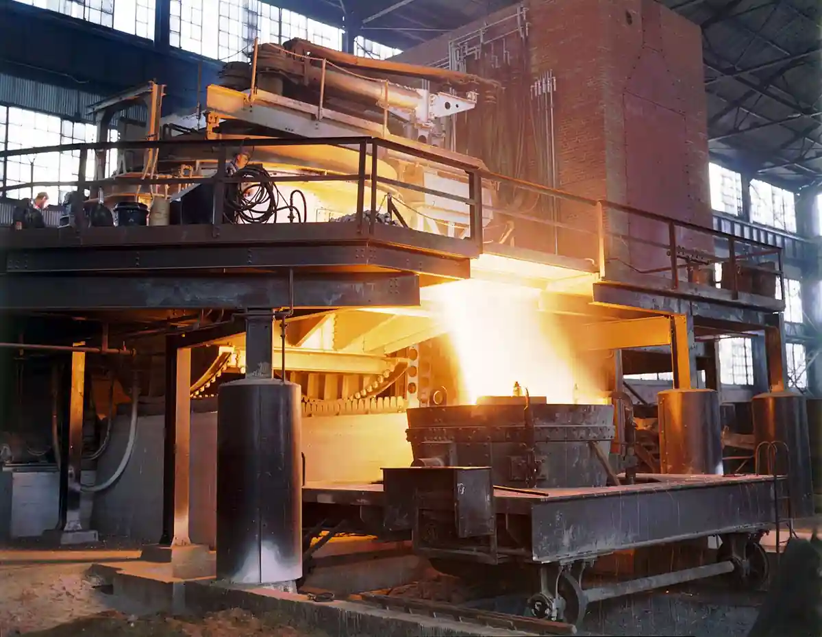
An electric arc furnace (EAF) melts metal scrap and direct-reduced iron using an electric arc struck between graphite electrodes and the charge. It is the primary melting unit of the mini-mill steel industry and, in smaller foundry sizes, a bulk melter for iron and steel castings where alloy flexibility and heat sizes from a few hundred kilograms upward matter more than the gentle chemistry control of an induction furnace.
Specifying an EAF means committing to a power infrastructure, an electrode supply chain, and an emission control system, not just a vessel. The datasheet lines that decide economics are specific energy in kWh per ton, tap-to-tap time, electrode consumption in kg per ton, and transformer rating in kVA per ton of capacity. This page decodes those lines, separates AC from DC designs, and maps the duty boundaries where an EAF wins over the competing melting furnace families.
The arc furnace sits in a product family with distinct siblings. The induction furnace melts with coil-induced eddy currents and dominates foundries below about 30 t; the cupola furnace melts iron continuously with coke; the crucible furnace and the gas aluminum melting furnace serve small-batch and low-melting alloys; the line frequency furnace and the holding furnace keep metal at temperature downstream. Each chapter here states plainly where the arc furnace beats them and where it does not.
An electric arc furnace is a power tool first and a furnace second: its output is set by transformer megawatts into the arc, its operating cost by electrodes and refractory per ton, and its permitting by dust and noise. This page gives the specifier the physics, the numbers, and the RFQ lines that separate a productive unit from an expensive one.
Chapter 1 / 06
What Is an Electric Arc Furnace
An electric arc furnace is a refractory-lined vessel with a removable roof, through which graphite electrodes descend toward the charge. The arc, a plasma channel at several thousand degrees Celsius, radiates heat directly into scrap below; oxygen lances and wall-mounted burners add chemical energy in modern practice. When the charge is molten and at aim temperature, the furnace tilts and metal runs through a tap spout into a casting ladle, which then feeds either a continuous caster or a foundry pouring line.
The selection question arises at a specific scale and mix. Above roughly 25 to 30 tonnes per heat and with cheap scrap available, the EAF's flat bath chemistry, oxygen capability, and high power density beat an induction furnace on productivity per square meter of shop floor. Below that scale, induction wins on yield, alloy loss, and the absence of electrode logistics. The buyer is therefore deciding simultaneously how big the heat should be, what the local electricity tariff and grid connection allow, and whether the plant's product mix needs the oxygen-based refining the arc furnace makes possible.
What is actually being decided in the specification is an energy balance. Melting steel scrap from cold to 1600 deg C requires a theoretical minimum near 385 kWh per tonne; real EAFs consume 360 to 500 kWh per tonne of electrical energy plus 30 to 50 Nm3 of oxygen and 5 to 15 kg of electrode carbon per tonne, with chemical energy from charge carbon and burner gas adding to the total. Every dollar of the business case is in the gap between the theoretical and the actual number, and every feature of a modern furnace, from foamy slag practice to water-cooled panels and hot metal charging, exists to close that gap.
The EAF also defines the plant around it. Its flicker and harmonics shape the electrical distribution, calling for a dedicated power transformer and often static var compensation; its dust load of 10 to 20 kg per tonne sets the size of the bag filter; its 100-plus dB melt noise sets the building acoustics. Downstream, the melt shop still needs a degassing unit for steel grades with hydrogen or inclusion limits, a shot blasting machine for castings cleaning, and heat treatment capacity, whose furnace requirements differ entirely; specifying the melter without its utilities is the classic first-project error.
Chapter 2 / 06
Working Principle and Furnace Types
AC arc furnaces
The conventional design passes three-phase alternating current through three graphite electrodes, one per phase. Each electrode arcs to the charge; current reverses 50 or 60 times per second, so no electrode is a lasting anode or cathode, and wear distributes evenly across the set. The secondary circuit from transformer to electrode is a massive low-voltage, high-current loop: a 100 t furnace runs secondary currents of 50 to 100 kA at 400 to 900 V, and the bus bars, flexible cables, and electrode arms are engineered as much for reactance minimization as for current carrying.
AC operation brings two side effects the specifier pays to manage. Arc current reversals make the arc wander, which raises flicker on the feeding grid and demands either a strong short-circuit capacity at the connection point or compensation equipment. And the three arcs pull toward each other electromagnetically, concentrating heat on the furnace wall between electrodes; wall panels, foamy slag covering, and burner placement all exist to even out that pattern.
DC arc furnaces
A DC furnace strikes a single cathode arc from one large electrode down to the melt, returning current through bottom anodes built into the hearth, either conductive refractory or vertical pins cooled in the bottom plate. One arc instead of three concentrates power density, cuts electrode consumption roughly in half (around 1 to 1.5 kg per tonne against 1.5 to 3 kg for AC on comparable duty), reduces flicker materially, and gives more uniform refractory wear. The costs are the bottom anode, which is a maintenance item AC does not have, and the rectifier station, which adds conversion losses and capital.
DC earns its premium where the grid is weak, where electricity is expensive enough that electrode savings matter, and on high-power single-arc duties like melting direct-reduced iron continuously. On straightforward scrap duty with a strong grid, AC remains the default industrial answer and holds most of the installed base.
The heat cycle
A modern heat runs in phases. Charging: baskets of scrap drop in with the roof swung aside, one to three baskets per heat. Melting: electrodes bore into the scrap, and the arc transitions from buried to open as a pool forms; oxygen lances cut the scrap and burn charge carbon, and wall burners preheat cold spots. Refining: with a flat bath, oxygen and carbon injection create a foamy slag that shields the arcs, raising power transfer efficiency and protecting the walls. Tapping: the furnace tilts typically 10 to 15 degrees toward the spout, and a slide gate or tilting spout controls the stream into the ladle. Tap-to-tap time, the master cycle metric, runs 35 to 60 minutes on modern scrap furnaces; every minute saved is a productivity and refractory win, because refractory wear is largely time-at-temperature.
Auxiliary systems set real output ceilings. Electrode regulation, which moves electrodes meters per second to hold arc current or impedance setpoints, decides stability at high power. Water cooling on roof and panels removes 5 to 15 percent of input power as heated water and lets the walls survive where brick would not. Off-gas evacuation, via a fourth-hole duct in the roof or a full doghouse enclosure, keeps the shop visible and the bag filter fed; combustion air control in the duct also burns CO before it reaches the filters.
Where the melt goes: casting routes
The arc furnace's output decides the casting route downstream, and the specification should be written with that route in view. Steel taps feed foundry lines pouring sand molds or centrifugal tubes, with a casting ladle fleet sized to the heat; the furnace does not pour, it delivers. Shops that also run light-alloy die casting keep a separate melting line entirely: an aluminum charge moves from melting through a degassing unit into a die casting machine or a cold chamber machine for high-pressure work, a route with its own thermal cycle measured in seconds, not heats. Confusing the two melting problems in one specification is how projects buy the wrong vessel: iron and steel duty belongs to the arc, induction, and cupola families; aluminum and zinc high-pressure duty belongs to the crucible, tower, and induction families feeding the die cell.
Heat economics also differ by product. A sand foundry taps 8 to 20 heats a day and every tap schedules molding lines, shakeout, and cleaning, so tap-to-tap regularity is worth more than peak speed. A billet or long-product mill, by contrast, runs the caster continuously and wants the shortest defensible tap interval with a hot heel practice. The same furnace hardware serves both; the control strategy, hold times, and refractory plan do not.
Chapter 3 / 06
Construction, Materials, and Duty Boundaries
Vessel and refractory
The shell is a heavy steel plate cylinder with a spherical or conical bottom, sized so the hearth holds the full heat with freeboard for foaming slag. Inside, the working lining follows zones: the hearth uses magnesia or doloma ramming and brick over a safety lining; the slag line, the most attacked ring, uses high-grade magnesia-carbon brick; the walls above slag line are water-cooled panels with thin castable or no refractory at all, a design that trades a small constant heat loss for much longer wall life. Roofs are water-cooled panels with a central triple (or single) electrode port ring of high-alumina castable. Refractory consumption on scrap duty runs 2 to 8 kg per tonne; slag practice, oxygen volume, and tap temperature move it more than brand choice does.
Electrodes and arms
Electrodes are extruded graphite, regularly tapered-jointed into columns above the furnace, diameters from 200 mm on small foundry furnaces to 700-plus mm on large melt-shop units. They are consumed by oxidation, tip sublimation, and breakage; a break loses a whole column section into the bath. The arms carry clamps, water-cooled conductors where the arm is conducting in modern designs, and position cylinders; regulation response is in the range of a few hertz with electrode travel speeds up to several meters per minute on the regulating axis.
Utilities and safety hardware
The transformer is the cost anchor: a furnace transformer handles severe cyclic duty, on-load tap changing across tens of secondary steps, and is built to furnace standards rather than distribution standards. Between grid and transformer, a reactor or compensator shapes flicker. Hydraulic or electro-mechanical tilt systems pour the heat; slide gates on the ladle and a tilt-control chair make the tap safe. Enclosures, from roof hood to full doghouse, are both emission and noise hardware; the bag filter behind them typically sees 10,000 to 100,000 m3/h of gas depending on furnace size, at dust loads that require efficient pulse-jet cleaning to meet the usual 10 to 20 mg/Nm3 stack limits.
Duty boundaries
State plainly where the EAF is the wrong machine. Below about 10 to 15 t per heat, electrode handling, arc instability in small baths, and the fixed cost of the electrical station make an induction furnace strictly better; foundry iron below 5 t is crucible or induction territory outright. For aluminum and zinc, arc heating is never competitive; the gas aluminum melting furnace and induction hold that ground with an order of magnitude lower melting temperature. Where the duty is holding and superheating rather than melting, a holding furnace or a line frequency furnace does it cheaper than keeping an arc lit. And where the product is clean steel castings with tight inclusion limits, the EAF is only the first stage: the ladle metallurgy and a degassing unit decide whether the grade ships.
Scrap quality as a construction boundary
Charge quality sets physical limits the furnace design cannot absorb. Heavy plate and structural scrap melts in stable cave-ins; shredded and baled stock carries oils and moisture that raise hydrogen, explode against the bath, and load the off-gas train with volatile organics. Direct-reduced iron shifts the problem to continuous feeding and gangue chemistry, requiring a hot metal or hot briquette strategy and a slag plan for its oxide load. The furnace specification should therefore name the charge mix band it is designed for, including bulk density and contamination limits, because roof design, gas cleaning capacity, and even electrode regulation tuning all sit on that assumption. A furnace bought for clean heavy scrap that later sees flammable shredder feed pays for the mismatch in electrode breaks and filter fires.
Chapter 4 / 06
Key Specification Parameters
The decode table lists the lines that decide whether a quoted furnace meets the production plan, with the catalog spread and the meaning of each at the plant level.
Parameter
Foundry scale, 5 to 30 t
Mill scale, 50 to 150 t
What it decides
Nominal heat size
5 to 30 t
50 to 150 t and above
Shop logistics, ladle size, caster match
Transformer rating
3 to 25 MVA
40 to 120 MVA
Specific power, hence melt speed ceiling
Specific power
300 to 500 kVA/t
500 to 1000 kVA/t
Tap-to-tap time band achievable
Electrical energy
420 to 550 kWh/t
360 to 430 kWh/t
Dominant variable operating cost line
Electrode consumption
2.5 to 4 kg/t (AC)
1.2 to 2.5 kg/t (AC), 1 to 1.5 (DC)
Second operating cost line plus supply risk
Oxygen input
10 to 25 Nm3/t
25 to 45 Nm3/t
Refining capability and energy offset
Tap-to-tap time
60 to 120 min
35 to 60 min
Daily heat count, labor productivity
Refractory consumption
5 to 10 kg/t
1 to 5 kg/t
Lining campaigns, downtime windows
Off-gas volume
10,000 to 40,000 m3/h
40,000 to 100,000+ m3/h
Bag filter size and fan power
Flicker duty at PCC
Pst 95th pct per IEC 61000-3-7
same planning levels, larger steps
Grid connection approval, compensation
Three of these lines carry the business case. Electrical energy per tonne moves directly with tap-to-tap discipline: every extra minute of flat-bath arc time before tap adds several kWh per tonne. Electrode price cycles make the consumption line volatile in cash terms, which is why DC's half-consumption argument returns whenever electrode prices spike. And specific power fixes the plant's ceiling: a furnace transformer undersized for the intended heat size cannot be tuned into modern productivity later; it is the least reversible line on the datasheet.
Read the electrical lines as a system. Transformer MVA only becomes arc power through the secondary circuit: every milliohm and every microhenry of bus, cable, and arm costs reactive volts and heating, which is why furnace builders obsess over conductor geometry and phase equality. Tap range decides operating flexibility across the melt stages, bores and melt on low taps, flat bath and refine on high. When comparing quotations, normalize both to power at the terminals per tonne and to the guaranteed energy number at a stated power factor; nameplate MVA alone flatters the unit with the worse secondary design.
The guarantee boundary matters as much as the guarantee value. Energy per tonne measured at the transformer primary includes regulation and bus losses; measured at the metering point it can hide them. Electrode consumption counted as weight delivered to the furnace includes joint losses and breakage, while a tip-only count flatters practice. Write the measurement method into the acceptance clause for each guaranteed number, and attach the charge mix definition, because every vendor table assumes one.
The second table maps the balance sheet of a representative 30 t foundry EAF per tonne of good taps, using typical ranges rather than any single vendor's promise; fill actual local tariffs to make it a decision table.
Cost element
Typical range per tonne
Notes
Electrical energy
420 to 550 kWh
At local industrial tariff; demand charges extra
Electrodes
1.2 to 4 kg
Grade UHP; DC at the low end
Oxygen and charge carbon
10 to 45 Nm3 O2; 5 to 15 kg C
Also burner gas where fitted
Refractory and consumables
2 to 10 kg equivalent
Slag line brick, ramming, guns
Electrode and shell cooling water
1 to 3 m3 processed
Closed circuits reduce this to makeup
Labor and maintenance provision
Plant specific
Electrode changes, gunning days, rebuilds
Chapter 5 / 06
Selection Decision Factors
Work the decision in this order; each step either fixes a number or eliminates a design.
Fix the product mix and heat size: grade family, annual tonnes, and the heat size that matches the ladle and downstream units. The heat size sets everything downstream.
Check the grid: available short-circuit power at the connection point, flicker and harmonic planning levels, and tariff structure including demand charges. A weak grid points at DC or compensation; a hard tariff on peak demand points at lower specific power with more hours.
Choose AC or DC on the arithmetic: electrode savings plus flicker relief against rectifier capital and bottom anode maintenance at your heat size.
Size the transformer for the tap-to-tap target, not the nominal tonnage: productivity is specific power. Leave physical space and tap range for a later power upgrade.
Set the scrap or charge strategy: basket scrap, shredded, direct-reduced iron pellets, or hot metal share; this drives bucket logistics, nitrogen and phosphorus chemistry, and energy per tonne.
Specify the emissions train as a system: fourth-hole or doghouse, combustion control, spark arrestor, and bag filter sized to the off-gas line above with a stack test plan.
Plan refractory campaign maintenance: slag line gunning windows, panel maintenance, and hearth survey cadence, matched to the production calendar.
Price total ownership over ten years: energy, electrodes, oxygen, refractory, and electrode-breakage insurance stock, not the furnace shell quote alone.
The cost comparison table shows the honest structure of a greenfield decision for a 200,000 t per year scrap-based shop; the same shape holds at foundry scale with smaller absolute numbers.
Decision element
EAF route
Induction route at same tonnes
Heat size for this output
40 to 60 t
10 to 20 t x multiple units
Specific energy
380 to 480 kWh/t
520 to 650 kWh/t
Electrodes
1.2 to 2.5 kg/t
none
Alloy and melt loss
higher oxidation losses
low loss, better for alloys
Grid requirements
flicker and harmonics management
harmonics from converters only
Emission system
major: bag filter train
small roof emission capture
Grade flexibility
oxygen refining, wide carbon range
limited refining, melt-and-hold
What to write in the RFQ, verbatim:
Duty: annual tonnes, heat size band, grades and tap temperature range, hours per day.
Electrical: available short-circuit MVA at the PCC, permitted Pst and harmonic levels, tariff including demand charge.
Performance guarantees: kWh per tonne, electrode kg per tonne, tap-to-tap minutes, refractory kg per tonne, at a stated charge mix and hot heel practice; test method and measurement boundary for each.
Furnace: AC or DC, shell size, transformer MVA and tap range, secondary current and voltage, electrode diameter, cooling water flows and temperatures.
Emissions: off-gas volume and temperature at the filter inlet, guaranteed stack dust concentration, noise envelope at stated distances.
Auxiliaries in scope: electrode regulation, oxygen lances and burners, tilt system, roof swing, ladle and slide gate, instrumentation package.
Acceptance: heat-by-heat energy and electrode audit over an agreed trial period at handover, plus grid compliance measurements.
Two clauses deserve disproportionate negotiation effort. First, the charge-mix annex: state bulk density bands, contamination limits, and the share of each scrap class the guarantees assume, so a later shift to cheaper feed does not void the energy guarantee or, worse, silently void the refractory one. Second, the utilities scope line: cooling water quality and flow, compressed air, and the emergency water connection for a power trip are preconditions of every thermal guarantee; if the builder supplies skids, tie their acceptance to the same heat log. Furnace disputes almost never argue about the shell; they argue about boundary conditions that were never written down.
Chapter 6 / 06
Field Practice: Commissioning, Standards, and Maintenance
Commissioning
Commissioning an EAF is staged: dry checks of tilt, roof swing, and electrode regulation; water and hydraulic circuits proven at flow; refractory dry-out and sintering cure on a documented ramp; then low-power heats on light scrap, raising power in steps while electrode regulation is tuned. Grid compliance measurements, flicker and harmonics at the PCC, are taken during the early heats and again at full power; these tests against the connection agreement are as much a part of acceptance as any thermal number.
Performance acceptance is a data exercise, not a demonstration: log every heat's kWh, oxygen, electrode weight change, tap temperature, and delays for an agreed number of heats at the contract charge mix. The guarantees in Chapter 5 are only meaningful if measured on this log, with the measurement boundary stated (transformer primary or secondary metering, for instance).
Operator training and the hot-start discipline belong in the acceptance plan too. Regulator tuning, burn-through recovery, and electrode-splitting technique differ between AC and DC and between charge types; a crew trained on the commissioning heats, with written emergency procedures for roof fires, water leaks, and stuck electrodes, protects the guarantee numbers for years after the vendor engineers leave. Plants that skip this line in the contract routinely give back several kWh per tonne within the first quarter as practice drifts.
Failure modes
The recurring failure modes are legible in shop data. Electrode breakage spikes trace to scrap caves collapsing on columns, wet scrap causing steam eruptions, or clamp and nipple torque drift; each break costs a column section and minutes of power-off time. Refractory wear concentrates at the slag line and electrode hot spots; the cure is slag chemistry (MgO saturation and basicity), gunning cadence, and panel flow checks, not thicker brick alone. Water leaks from cooled panels or roof boxes are the safety-critical item: any leak above the bath risks a steam explosion, so daily panel inspection and a strict no-leak-run rule are standard. In the electrical room, furnace transformer and cable failures correlate with dust ingress and cooling water conditioning; the arc welder next door is not the risk, but the same conductive dust attacks both.
Maintenance cadence
Daily: panel and roof visual checks, electrode column inspection, oxygen lance function, off-gas temperatures and filter differential pressure review. Weekly: clamp torque and contact resistance, hydraulic oil sample trends, tilt brake test. Campaign-based: slag line gunning or brick replacement every one to four weeks by duty, roof panel and port ring rebuild every few months, hearth survey by laser or template monthly with gunning as indicated. Annual: transformer oil analysis and dissipated-gas check, bus system thermographic survey under load, regulator response verification, and a full safety interlock test including the emergency roof swing and tilt limits.
Standards to write into the file: IEC 60519-1 with its furnace-part sections for safety in electroheat installations, IEC 61000-3-7 for flicker and rapid voltage change assessment at the planning level, and the local stack emission and noise permits that name the bag filter guarantee. Procurement should also hold the electrode supplier to a defined graphite grade specification with joint/nipple performance, because electrode failures appear in the furnace's numbers, not the electrode maker's.
The melt shop context completes the picture: EAF taps feed a casting ladle fleet whose refractory and preheat discipline sets yield; castings route through a shot blasting machine and often a heat treatment furnace, both with their own energy lines; and foundry sands loop through a sand reclamation unit whose economics improve with every reduction in melt-related sand burn-on. The furnace is the heart of the shop, but its uptime is written in the maintenance calendar of everything around it. Keep the arc furnace's own log, heat by heat, next to those calendars: the trend lines for energy, electrodes, and refractory are the earliest warning the plant will ever get, and they cost nothing but the discipline to record them.
FAQ
What heat size makes an arc furnace better than induction melting?
The crossover sits near 20 to 30 tonnes per heat. Below it, induction furnaces win on alloy yield, melt loss, and the absence of electrode and bag-filter systems. Above it, the EAF's power density, oxygen refining, and single-vessel productivity dominate, and per-tonne energy closes the gap even though induction is quieter on emissions. The exact point moves with local electricity tariffs, scrap density, and product mix.
How much electricity does an EAF use per tonne, and what moves the number?
Modern scrap EAFs consume 360 to 500 kWh per tonne; the theoretical minimum near 385 kWh for cold scrap means the best plants ride the floor with hot charge, foamy slag practice, and tight tap discipline. Adding 60 kWh per tonne is easy: extended flat-bath time before tap, poor scrap density causing long melts, and low oxygen use are the three usual causes found in heat logs.
Should I buy AC or DC for a new melt shop?
Choose DC when the grid connection is weak (flicker limits bite), electricity and electrode prices are high, or the duty is continuous DRI melting; electrode consumption near 1 to 1.5 kg per tonne is the signature benefit. Choose AC when the grid is strong and capital discipline rules: the installed base is larger, the rectifier station and bottom anode maintenance disappear, and three-electrode practice is what most operating crews know.
What actually drives electrode consumption, and can I control it?
Consumption splits into tip sublimation, sidewall oxidation, and breakage. Sidewall oxidation scales with off-gas excess air and time above the bath, so hooding and combustion control pay directly; breakage is scrap-preparation and clamp-maintenance discipline; tip loss follows arc current and power-on time per tonne. Buying to 2 kg per tonne on AC with good practice is normal; 4 kg per tonne says the process, not the electrode, is the problem.
What are the real permitting pain points for an EAF project?
Three files decide the schedule: the grid connection study, because flicker and harmonics from arc operation must meet planning levels at the connection point; the air permit, because bag filter performance and stack dust testing must be guaranteed; and noise, because melt arcs exceed 100 dB and enclosures become building design. Starting these files after the furnace contract is signed is the most common cause of slipped startups.
How long does a refractory campaign last, and what is the maintenance rhythm?
On foundry EAFs expect slag line attention every one to four weeks and hearth campaigns of hundreds of heats with gunning maintenance; mill-scale furnaces with foamy slag and panel walls run equivalent or better. The operating rhythm is daily panel checks, weekly clamp and lance service, campaign gunning windows, and a monthly hearth survey. Campaign life moves most with slag basicity, MgO saturation, and tap temperature discipline.
Is an EAF a good choice for melting aluminum or copper alloys?
No. Arc heating's advantage is power density at steel temperatures; aluminum melts at 660 deg C where combustion and induction deliver heat at far lower cost and cleaner metal. Aluminum shops use a gas aluminum melting furnace or induction; copper and brass foundries use induction or crucible furnaces. The EAF earns its place in iron and steel, and in ferroalloy and some recycling duties, not in low-melting non-ferrous shops.