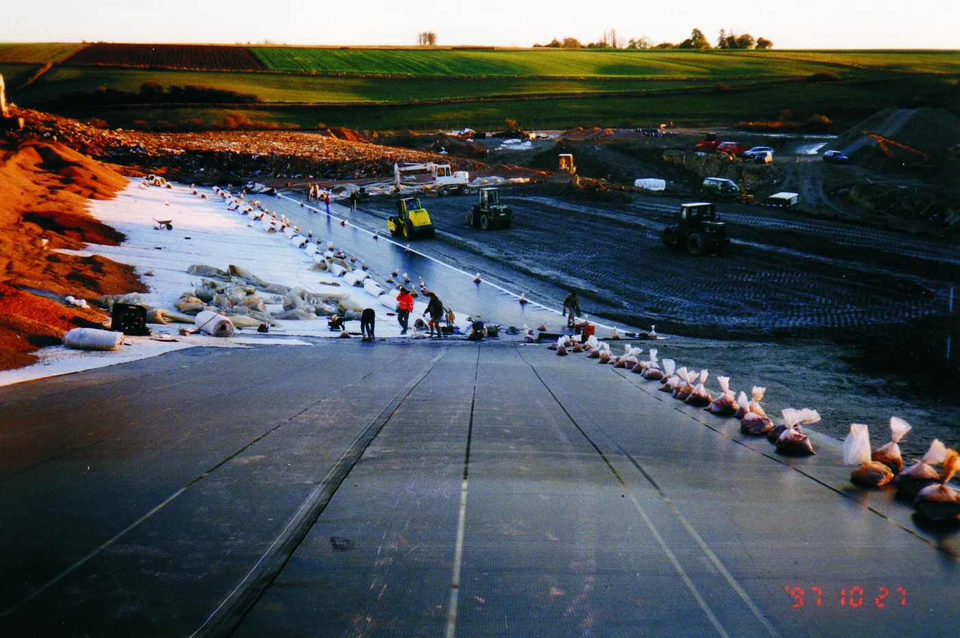
HDPE Geomembrane Thickness Selection for Landfill Liners and Covers
A landfill barrier is not a masonry wall. Nobody builds a containment layer from block brick or AAC block and nobody can inspect it after waste is placed: the working barrier is a black polyethylene sheet between 1.0 and 2.5 mm thick, welded from rolls in the field, buried once, and trusted for decades. Selecting its thickness is therefore a one-shot decision governed by regulation on one side and by puncture, slope, and seaming physics on the other, and it is the single specification line that most changes the installed cost per square meter.
This page is written for the engineer or buyer who must write the liner and cover specification and defend it to a regulator. It sets out where each thickness belongs across base liners, final covers, and side slopes; how the polymer and the seams actually work; the smooth versus textured decision; the GRI GM13 and ASTM property table decoded line by line; an ordered selection sequence with a 40 versus 60 mil cost comparison; and the field practices, from subgrade preparation to seam testing, that decide whether the purchased thickness survives installation.
This guide is aimed at civil and geotechnical engineers, CQA professionals, and procurement teams specifying landfill containment. It covers 6 chapters from regulatory minima and liner physics through product types, the GRI GM13 property table, a selection sequence with cost comparison, and field practice. Standards referenced include ASTM D5199, D5994, D1505, D639, D6693, D1004, D4833, D5514, D1603, D3895, D5885, D5397, D5321, D6392, D5641, D5820, and GRI GM13, plus the US federal rule 40 CFR 258.
Chapter 1 / 06
The Thickness Question: Liner, Cover, or Collection Layer
Thickness selection starts by naming the layer being specified, because the same polymer sheet does four different jobs in one landfill cell. The base liner sits under the waste, carries the gravel leachate collection layer on top of it, and takes construction traffic while that gravel is placed. The final cover sits over the waste, decades later, in a shallower and colder environment but on a settling subgrade. Side slope panels hang on 3H:1V or steeper inclines, where the governing physics is friction, not puncture. And beneath or beside the geomembrane, the drainage and detection layers move leachate to a sump. A 40 mil sheet that is defensible on a flat cover can be indefensible on a base liner under gravel, and the regulatory floor draws exactly that line.
In the United States the federal floor for municipal solid waste is the composite liner rule in 40 CFR 258.40: a geomembrane upper component over a lower component of at least 600 mm (2 feet) of compacted soil with a hydraulic conductivity no greater than 1 x 10 to the minus 7 cm per second. Within that rule, the flexible membrane liner must be at least 30 mil thick generally, and at least 60 mil (1.5 mm) where the liner material is high density polyethylene, which in practice it almost always is. State programs can and do go stricter, and many states add their own design and CQA requirements on top, so the federal number is a floor to check against, never the specification itself.
Covers are treated differently. The federal final cover rule for MSW is performance based: an infiltration layer no more permeable than the composite liner system or its equivalent, plus an erosion layer. It does not name a geomembrane thickness, and some cover designs use compacted clay alone. Where a geomembrane is used in the cover, 40 mil (1.0 mm) is the common design choice, and state programs that do specify numerically land in the same region: New York, for example, requires a cover barrier of at least 40 mil if it is LLDPE or at least 60 mil if it is HDPE, the HDPE minimum existing largely for seaming reasons. That is a useful signal for specifiers: HDPE cover sheet below 60 mil welds poorly in field conditions, and regulators know it.
It helps to keep the analogy boundary clear. A building waterproof membrane or a roof applied modified bitumen membrane is a weathering product, exposed to thermal cycling and UV, serviceable and replaceable over a building life. A landfill geomembrane is a buried containment product: once waste is placed, it cannot be inspected or economically replaced, so the specification has to survive construction damage, waste loading, and chemical exposure on one pass. That asymmetry is why the property table in Chapter 4 exists and why buyers should treat datasheet marketing values with less weight than a published minimum-average standard such as GRI GM13.
The table below maps the decision in one view. Read it as the answer to "which thickness where", then use the rest of the page to challenge each row against your project specifics.
Application
Typical HDPE thickness
Governing load or rule
Notes for the specifier
MSW base liner, composite
60 mil (1.5 mm) minimum
40 CFR 258.40 federal floor, state rules stricter
Smooth on floor, textured up slopes
MSW final cover barrier
40 mil (1.0 mm) common
Performance rule, state numeric minimums where set
60 mil if HDPE in stricter states, for seaming
Side slopes, 3H:1V and steeper
40 to 60 mil, textured
Veneer stability, interface friction
Texture both sides where soil covers both faces
Leachate collection under-drain layers
Not geomembrane duty
Geonet or gravel with perforated pipe
Specify pipe and geotextile separately
Hazardous waste containment
60 to 100 mil
RCRA Subtitle C programs, chemical service
Thicker for aggressive leachate and double liners
Wastewater and decorative ponds
30 to 40 mil
Puncture and exposure, not MSW rules
30 mil acceptable only outside MSW duty
Chapter 2 / 06
How an HDPE Liner Actually Works
The sheet starts as a resin. Geomembrane-grade high density polyethylene is formulated to a density of about 0.940 to 0.960 grams per cubic centimeter, well above the 0.941 threshold that defines the high density class, and is compounded with 2 to 3 percent carbon black for UV screening plus a package of antioxidants and stabilizers whose depletion rate, more than any mechanical property, sets the service life of a buried liner. The compound is extruded or blown into flat sheet and slit into rolls, typically about 7 m wide and 100 to 200 m long, with thickness controlled at nominal values of 30, 40, 60, 80, or 100 mil (0.75, 1.0, 1.5, 2.0, or 2.5 mm).
The containment logic of the composite liner is worth stating precisely, because it explains why the geomembrane can be so thin. Compacted clay alone has low but nonzero permeability; a defect-free polyethylene sheet is effectively impermeable to water but can have manufacturing and construction defects. Combining them means flow through any geomembrane defect must exit through the clay layer, where the wetted area is small and the flow path is long, cutting leakage rates by orders of magnitude compared with either component alone. The geomembrane carries almost no structural load; it is a diffusion and advection barrier draped over an engineered soil formation, which is why subgrade quality appears ahead of thickness in the selection sequence of Chapter 5.
Thickness earns its cost during construction. A drainage blanket of graded gravel, commonly 300 mm thick with stones up to 30 mm or more, is dumped and dozed directly over the liner with only a protection geotextile or a sand layer in between. A dozer walks on that blanket while spreading it. Laboratory index tests show puncture resistance rising almost linearly with thickness: the GRI GM13 minimum for the DIN-style pyramid puncture test, ASTM D4833, moves from 54 lbf at 40 mil to 81 lbf at 60 mil, and large-scale tests such as ASTM D5514 on real gravel show the same direction with more scatter. Field experience matches: most liner damage reports trace to gravel placement and traffic on thin sheet, not to waste loading after the collection layer is built.
The seams are where a sheet becomes a barrier, and thickness changes the welding operation itself. Panels are joined by double-wedge fusion welding: a hot wedge melts two parallel tracks while a roller presses the sheets together, leaving an unwelded air channel between the tracks that is pressurized to prove continuity of every meter of seam. Extrusion welding, where molten polyethylene rod is fused over a prepared overlap, is reserved for repairs, patches, pipe penetrations, and T-seam intersections that the wedge cannot reach. Both processes are slower and less forgiving on thin sheet: at 30 mil, a wedge welder runs on the edge of its process window and a hand-held extrusion gun can overheat and thin the parent material. This is the practical reason the 60 mil federal floor for HDPE base liners exists, and it applies with full force to any HDPE cover sheet a project might consider at 40 mil.
Around the liner, the rest of the containment system is built from materials the specifier buys on the same purchase order. Leachate collection laterals are perforated HDPE, the same polymer family as PE pipe used in pressure and drainage service, sized and perforated per the leachate generation model, and the collection header is a larger solid-wall plastic pipe run to the sump through the liner penetration, which is itself a welded boot detail. Each penetration, sump collar, and concrete vault interface is a leak path, which is why Chapter 3 treats structure connections and Chapter 6 treats their QA.
What the sheet does not do is absorb differential movement. HDPE geomembrane has high tensile strength but works as a membrane: its bridging of a void or a settling zone mobilizes tensile stress that must stay below the yield values in Chapter 4 with a safety factor. Waste settlement under a final cover, subgrade washouts under a base liner, and slope creep are all handled by the soil design, not by asking more thickness from the polymer. Thickness buys puncture resistance and weldability; it does not buy extensibility, and a design that relies on stretch has a different problem.
Chapter 3 / 06
Product Types and Duty Boundaries
The first product fork is smooth versus textured. Smooth HDPE sheet is the default for flat floors and gentle slopes: it is cheaper per square meter, its thickness and mechanical minimums in GRI GM13 are slightly higher because no material is consumed in texturing, and every welding process is at its best on it. Textured sheet carries impressed asperities, usually by the nitrogen-bubble or co-extrusion process, on one or both surfaces, and exists for one reason: interface friction. A smooth HDPE surface against a drainage geotextile or sand layer typically tests at interface friction angles of about 8 to 12 degrees, low enough that a veneer of soil or drainage layer slides on a 3H:1V slope (18.4 degrees) under its own weight. Textured surfaces test at roughly 20 to 30 degrees against common geosynthetics and soils, which is what makes cover soils and drainage layers stay put on landfill side slopes.
Texture placement follows the layer stack. On a base liner floor, smooth sheet is standard because the slope is flat and welding is easiest. Up the side slopes, textured-on-both-sides is common where a geotextile or geonet sits below and soil or gravel sits above, so both interfaces need friction. On final covers, texture often goes on the upper face only, against the cover soil, while the lower face rides on a smooth gas collection layer. The decision is made from large-scale interface direct shear testing per ASTM D5321 on the actual project materials, not from manufacturer brochures, and Chapter 5 puts that test on the critical path.
The second family is structured surfaces: spiked or studded sheet, profiled blocks, and drainage composites integrally formed with the membrane. Structured products combine containment with in-plane drainage or gas collection, replacing a geonet layer in some cover systems. They are legitimate products with real cost trade-offs, but they are specialty items: their interface and hydraulic properties are product-specific, so they are specified by performance testing on each project rather than by the GM13-style commodity table, and they sit outside the scope of the standard liner detail most buyers are writing.
The thickness classes map onto duty as follows. At 30 mil (0.75 mm), HDPE is a thin-film product for secondary containment around tanks, decorative and temporary pond duty, and vapor barriers; under US MSW rules it cannot serve as the composite liner geomembrane, and its welding margin is thin. At 40 mil, HDPE is the common cover and lagoon sheet, workable by fusion welding with competent crews in moderate weather. At 60 mil, the sheet is the MSW base liner standard and the default for any duty with gravel placement, sustained traffic, or multi-decade unrecoverable service. At 80 and 100 mil, the market is hazardous waste containment under RCRA Subtitle C programs, heap leach pads, and secondary containment for aggressive chemistry, where the added puncture margin and chemical residence time justify the material cost.
The composite options underneath finish the classification. Below or beside the compacted clay layer typically 600 mm thick, a geosynthetic clay liner, a factory-made sandwich of bentonite clay between geotextiles that hydrates to low permeability, substitutes for clay where borrow material is scarce; regulators accept it in defined configurations, but it does not replace the geomembrane, it replaces part of the soil component. The liner system as purchased is therefore a stack: prepared subgrade, clay or GCL, smooth or textured geomembrane, protection geotextile, drainage gravel or geonet with its perforated pipe, and cover soil, and the thickness decision interacts with every layer above it.
Structure connections are their own boundary condition. Where the liner meets a concrete sump, vault wall, or pipe collar, the geomembrane cannot be cast into concrete and left to flex: the detail uses a batten and gasket mechanical termination or a chemical anchor termination, and where concrete joints occur in the structure, conventional cast-in waterstop products and sealed expansion joint assemblies carry the structure-side sealing duty while the geomembrane boot handles the polymer-to-concrete transition. Specifiers should detail these terminations explicitly in the drawings, because they are the least standardized, most installation-sensitive components in the system, and they appear on almost every project.
Attribute
Smooth HDPE sheet
Textured HDPE sheet
Typical duty
Flat floors, gentle slopes, lagoon covers
Side slopes 3H:1V and steeper, veneer stability
Interface friction angle vs geotextile
About 8 to 12 deg
About 20 to 30 deg
GRI GM13 mechanical minimums
Full values, e.g. 126 lbf/in yield at 60 mil
Slightly reduced, texture consumes cross section
Welding speed and margin
Best case for wedge fusion
Slightly slower, texture burns at weld edges if mis-set
Material cost per square meter
Baseline
About 5 to 15 percent above smooth
Selection evidence
Default where slope stability is not governing
Require ASTM D5321 interface shear on project materials
Chapter 4 / 06
Key Specification Parameters
The decode table below is the buyer's side of the conversation with a geomembrane manufacturer. Every line is anchored to a standard test method, and the numeric column follows the structure of GRI GM13, the Geosynthetic Institute's standard specification for HDPE geomembranes, which lists minimum average values per property per thickness together with the required test methods and testing frequency. Treat GM13 as the floor of your purchase specification: a datasheet that shows only typical values, omits the test method, or omits the testing frequency is not a comparable document, and Chapter 5 makes the GM13 certificate a deliverable.
Specification line (test method)
GM13 minimum, 40 mil smooth
GM13 minimum, 60 mil smooth
What it means for selection
Nominal thickness (ASTM D5199; D5994 for textured)
40 mil (1.0 mm) min average
60 mil (1.5 mm) min average
Conformance samples measured with a calibrated thickness gauge on a firm plate
Density (ASTM D1505)
0.940 g per cm3 min
0.940 g per cm3 min
Confirms high density resin class and chemical resistance
Tensile yield strength (ASTM D639, D6693)
84 lbf per inch of width
126 lbf per inch of width
Stress the sheet can carry before yielding; seam shear must match
Tensile break strength (ASTM D639, D6693)
114 lbf per inch
171 lbf per inch
Ultimate strength; the margin above yield is the rupture reserve
Tear resistance (ASTM D1004)
19 lbf
28 lbf
Resistance to tear propagation from a cut or stone point
Puncture resistance (ASTM D4833)
54 lbf
81 lbf
Index for stone and gravel puncture; field scale via D5514
Carbon black content (ASTM D1603)
2.0 to 3.0 percent
2.0 to 3.0 percent
UV screening for exposed phases; not a weathering lifetime guarantee
Carbon black dispersion (ASTM D5596)
Category 1 or 2 in about 9 of 10 views
Category 1 or 2 in about 9 of 10 views
Poorly dispersed black screens badly and signals poor compounding
Standard OIT (ASTM D3895)
100 min
100 min
Antioxidant reserve; depletion rate governs embrittlement life
High pressure OIT (ASTM D5885)
400 min
400 min
Alternative antioxidant measure for modern stabilizer packages
NCTL stress crack resistance (ASTM D5397)
Project-specified, 200 h class typical
Project-specified, 200 h class typical
Slow crack growth resistance, the failure mode that matters long term
Asperity height for textured (ASTM D7466)
About 0.4 mm typical spec
About 0.4 mm typical spec
Texture geometry; friction data from D5321 must support the design
Values above are the GM13 structure of minimum averages for smooth sheet; textured sheet carries slightly lower tensile minimums because the texturing consumes cross-sectional area, and the current GM13 revision governs in any dispute, so verify against the live document at purchase. The habits that make this table work are three. First, demand conformance results per resin batch and per production lot at the GM13-stated frequency, not one certificate for the whole order, and have the independent CQA laboratory retest a defined sample on receipt; a calibrated thickness gauge and a tensile testing machine are the working instruments of that retest program. Second, read elongation numbers correctly: yield elongation around 12 percent and break elongation 700 percent or more are index values from dogbone specimens, not usable stretch in service. Third, keep OIT and NCTL on the purchase order even though they rarely gate delivery, because they are the two properties that correlate with whether the liner is still ductile in year 30.
For seams, the specification lines are different and are usually written into the construction QA plan rather than the material purchase: double-track fusion with air channel pressure hold, extrusion welds only at repairs and intersections, destructive tests cut at a stated frequency, and shear and peel acceptance values tied to GRI GM19-style minimums for the sheet thickness purchased. Chapter 6 gives the field execution; the point for Chapter 4 is that seam acceptance, unlike material properties, is verified on every project, so write the numbers into the contract documents rather than relying on installer goodwill.
Chapter 5 / 06
Selection Decision Factors
The sequence below is ordered the way a reviewer will attack the specification: regulatory floor first, then the physics of the site, then the economics. Each step either confirms the working thickness or sends you back one class, and no step after the first can legally reduce what the first step fixed.
Fix the regulatory floor for the named layer: 60 mil minimum for an HDPE geomembrane in a US MSW composite base liner under 40 CFR 258.40, 40 mil as the working common choice for covers subject to state numeric rules where they exist. Check the state program before anything else, because several states exceed the federal floor.
Characterize the subgrade: soil type, stone content, achievable compaction and smoothness. A subgrade that cannot be brought to the no-stones-above-12-mm standard of Chapter 6 argues for thicker sheet plus a geotextile protection layer, not against it.
Set the slope and interface requirement: for 3H:1V and steeper slopes, order large-scale interface direct shear testing per ASTM D5321 on the actual geomembrane, geotextile, and soil combination, then choose smooth or textured from the measured friction angles with the design safety factor, not from catalog ranges.
Define the drainage gravel gradation and placement method: maximum particle size, drop height, equipment weights, and whether a protection geotextile or sacrificial sand layer sits between gravel and liner. Coarser gravel dropped from height is the classic case that pushes 40 mil to 60 mil.
Load in the construction traffic: dozer crossings on the drainage blanket, foot traffic during pipe and sump work, and welding crew traffic on slopes. Every crossing is a local puncture test.
Review chemical service: normal MSW leachate is within HDPE's envelope, but process wastes, high temperature leachate above about 40 deg C, and hydrocarbon-affected sites argue for the thicker classes and for project-specific chemical immersion testing.
Write the seam QA plan and warranty together: seam testing frequency, destructive acceptance values, installer qualifications, and a material warranty keyed to the GM13 conformance certificates rather than to generic fitness-for-purpose language.
Price the installed system, not the sheet: material, welding labor, QA testing, and repair allowance move together with thickness, and the comparison below shows the shape of the deltas.
The cost comparison at 40 versus 60 mil illustrates why the decision is usually made on duty rather than on price. Indicative material pricing runs roughly 1.2 to 1.8 USD per square meter for 40 mil HDPE and 1.7 to 2.6 USD for 60 mil in large civil quantities, with textured surfaces adding about 5 to 15 percent. Welding productivity drops slightly on 60 mil because wedge speed is lower, and QA testing intensity is similar in both cases because it scales with seam length, which depends on panel width, not thickness. On a one-hectare cell with roughly 1,400 to 1,600 linear meters of field seam, the 60 mil choice adds on the order of 6,000 to 11,000 USD in material plus a modest welding premium, which is small money against a base liner's total installed cost and vanishingly small against a leak investigation.
Cost line, one-hectare lined area
40 mil HDPE
60 mil HDPE
Material, indicative
1.2 to 1.8 USD per m2
1.7 to 2.6 USD per m2
Material total, 10,000 m2 plus overlap
About 13,000 to 19,000 USD
About 19,000 to 29,000 USD
Field seam length at 7 m panels
About 1,400 to 1,600 m
About 1,400 to 1,600 m
Welding labor, fusion crew
Baseline
About 10 to 20 percent higher, lower wedge speed
QA testing, nondestructive plus destructive
Scales with seam length
Same length, same order
Regulatory acceptance for MSW base liner
Not permitted
Permitted floor
Puncture index, ASTM D4833
54 lbf
81 lbf
What to write in the RFQ, as a checklist. Name the layer, the governing regulation, and the state program. Specify thickness as a GM13 minimum average with the test method named, smooth or textured with texture faces and, for textured sheet, asperity height. Require GM13 conformance certificates per resin and per production lot with the testing frequency stated, and reserve the right to independent retest on receipt using a qualified laboratory with a tensile testing machine and calibrated dimensional equipment. Require roll dimensions, palletizing, staging requirements, and batch traceability marking. Require installer qualification statements, seam QA procedures referenced to the project CQA plan, and the warranty terms including whether they cover material only or material and installation. Ask explicitly for the resin source and country of manufacture, because GM13 conformance is meaningful only when traceable to a known compound, and require the manufacturer to state the GM13 revision against which values are certified.
Chapter 6 / 06
Field Practice: Deployment, Seaming, and CQA
Subgrade preparation is the first field practice because it protects thickness that has already been paid for. The prepared surface immediately under the geomembrane should be a smooth, compacted fine-grained layer with no stones larger than about 12 mm, no sharp debris, no standing water, and no desiccation cracks, proof-rolled and accepted in writing before any panel touches it. On slopes, the subgrade is cut and compacted to line so the panels lie without bridging or slack pockets. Any deviation found at panel deployment is corrected in the soil, not compensated in the liner.
Deployment itself is temperature work. Black HDPE expands strongly in sun: panels deployed hot grow lengthwise, and a panel welded at midday heat locks in waves and slack that later become folds under the drainage layer. Standard practice deploys and welds in the cooler parts of the day, sequences panels down-slope, allows thermal relaxation time before seaming, and accepts that in hot climates the welding window is early morning. Panel placement records, numbered panels, and a panel log that becomes the as-built panel map start here, because every later repair and test is referenced to them.
Anchor trenches hold the top of slope panels. A typical detail is a trench about 0.5 to 0.8 m deep and of similar width, cut back about 0.5 to 1.0 m from the slope crest, with the geomembrane run into it, temporarily ballasted, then backfilled and compacted with the excavated soil in lifts. The trench is soil work: it is never stabilized with grout, concrete, or dry mortar, because the geomembrane must remain able to take up strain, and a stiffened trench tears the sheet at the crest line instead of holding it.
Seam testing runs in two layers, nondestructive and destructive, and both are contractual. Nondestructive testing covers every meter of seam: double-track fusion seams get the air channel pressurization test per ASTM D5820, inflating the unwelded channel to a specified pressure and watching a timed pressure hold; single-track and extrusion seams and repairs get the vacuum box test per ASTM D5641 over a soap solution; patches and cap strips can additionally be spark tested along their edges. Destructive testing samples the weld itself at a stated frequency, commonly one sample per 150 to 300 m of seam length or per shift per crew: coupons are cut, the immediate hole is repaired and retested, and the coupons go to a tensile testing machine for shear and peel per ASTM D6392-style procedures.
Pass criteria deserve precision. Shear strength must meet or exceed the sheet's GM13 minimum for the thickness purchased, 126 lbf per inch of width at 60 mil. Peel values for fusion and extrusion seams are set as a defined fraction of sheet strength under the GRI GM19 framework, and the criterion experienced engineers watch hardest is the failure location: a passing seam fails in the parent sheet, the film tear bond condition, rather than peeling apart at the weld interface. An adhesive-bonded seam is not part of this system at all; HDPE liner seams are thermally welded, never glued with adhesives or bonded with dry mortar or tape products, which is one of the properties that lets a buried weld outlive its installer.
Repairs follow a fixed hierarchy: defects, holes, and failed test locations are repaired by grinding and extrusion welding a patch or cap strip with a 150 mm minimum overlap in all directions, then retested nondestructively, logged against the panel map, and added to the as-built record. Third-party construction quality assurance closes the system: an independent CQA engineer and laboratory witness subgrade acceptance, panel deployment, welding parameters, weather logs, every nondestructive test, and the destructive sampling chain of custody, and the CQA report is the document the regulator audits. Buyers arranging their own QC should mirror that structure at reduced intensity: verify GM13 certificates against received roll markings, spot-check thickness on rolls with a field thickness gauge at edges and center, and hold the installer to the logged repair record before final acceptance.
After placement, service life is a chemical-aging story. Buried at moderate temperatures, out of UV, with a well-compacted cover, HDPE geomembranes are projected in Geosynthetic Institute aging studies to remain ductile for timescales measured in centuries, with antioxidant depletion, tracked by OIT consumption, as the leading indicator of embrittlement onset. The enemies are heat and exposure: leachate temperatures above about 40 to 50 deg C accelerate depletion steeply, and long uncovered site phases burn UV screening margin. Specify a cover schedule that minimizes exposed liner time, and treat any project with hot waste or a long pre-waste phase as a case for the thicker classes and project-specific aging review.
FAQ
What is the legal minimum thickness for an MSW base liner in the US?
Under the federal rule 40 CFR 258.40, the composite liner geomembrane must be at least 30 mil as a flexible membrane liner generally, and at least 60 mil (1.5 mm) where the material is HDPE, which is nearly always the case. It sits over at least 600 mm of compacted soil with hydraulic conductivity no greater than 1 x 10 to the minus 7 cm per second. State programs may require more, so the federal figure is a floor to check against, not the specification.
Should the final cover geomembrane be 40 or 60 mil?
The federal MSW cover rule is performance based and does not name a thickness, so the choice follows state rules and engineering. Where HDPE is used, 40 mil is the common design thickness for covers, and stricter states set numeric floors: New York, for example, requires at least 40 mil for an LLDPE cover barrier and at least 60 mil where it is HDPE, the higher HDPE minimum existing for seaming reliability. Choose 60 mil where cover construction traffic or coarse drainage layers will load the sheet.
When is textured geomembrane mandatory?
Texture becomes mandatory whenever veneer stability governs, in practice on side slopes of 3H:1V and steeper where a cover soil, drainage layer, or geotextile interface must carry shear. Smooth HDPE against a geotextile tests near 8 to 12 degrees of interface friction, below an 18.4 degree slope angle, so the veneer slides; textured surfaces test near 20 to 30 degrees and hold. The decision is confirmed by ASTM D5321 large-scale interface shear on the actual project materials, not by catalog values.
What does GRI GM13 add over a manufacturer datasheet?
GM13 converts marketing typicals into a purchase-enforceable specification: named ASTM test methods, minimum average values per property per thickness, and the required frequency of conformance testing per resin and production lot. A datasheet showing one set of typical values with no method or frequency cannot be compared across suppliers or enforced at receipt. Buying against GM13 also gives the CQA laboratory a defined target for independent retest of thickness, tensile, puncture, carbon black, and OIT.
How are seams tested and what does a pass look like?
Every meter of seam gets nondestructive testing: air channel pressurization for double-track fusion seams per ASTM D5820, vacuum box testing per ASTM D5641 for extrusion and repair seams. In addition, coupons are cut at a stated frequency, commonly one per 150 to 300 m of seam, and tested in shear and peel on a tensile testing machine per ASTM D6392-style procedures. A pass meets the strength minimums, with shear at or above the sheet value, and fails in the parent sheet rather than the weld, the film tear bond condition.
What service life can a buried HDPE liner be expected to give?
In buried, moderate-temperature conditions with UV excluded, Geosynthetic Institute aging studies project ductile service lives for HDPE geomembranes measured in centuries, with antioxidant depletion tracked by OIT as the leading indicator of embrittlement. Elevated temperature is the main accelerator: leachate above roughly 40 to 50 deg C can cut projections by an order of magnitude. Buy margin with the cover system, minimize exposed time before burial, and treat hot-waste sites as cases for project-specific aging review and thicker classes.
Can 30 mil geomembrane ever be used in a landfill?
Not as the composite base liner geomembrane of a US MSW landfill: the federal floor is 60 mil for HDPE. Thinner sheet appears around the periphery of landfill projects, in secondary containment berms, temporary covers, vapor barriers, and some leachate conveyance details, and it is common in decorative ponds and canal work. On any landfill feature, check the state program before allowing 30 mil anywhere, because several states restrict even ancillary uses.