Induction vs Electric Arc Furnace Selection by Melt Duty
Most melt-shop equipment arguments are really arguments about melt duty that nobody wrote down. An induction furnace and an electric arc furnace both deliver liquid metal at pouring temperature, and both are bought with megawatts, but they reward completely different operating patterns: the induction route wins on alloy flexibility, chemistry control, and small-to-mid heat sizes; the arc route wins on throughput of a single alloy family, tolerance for dirty and bulky scrap, and scale economics. This page turns that split into numbers a buyer can defend in a capital request: energy per ton on a stated basis, electrode and refractory consumables, grid and permitting limits, and a chapter-by-chapter path from your alloy list to a signed specification.
The audience is the foundry engineer or plant buyer choosing melt capacity for iron, steel, copper-base, or aluminum programs, whether for a greenfield line, a capacity expansion, or an energy-driven retrofit. Each chapter ends in something actionable: a duty boundary to check, a datasheet line to demand with its basis, an acceptance test to write into the contract, or an RFQ input list that makes competing quotes comparable.
Induction melts by eddy currents induced in the charge itself; the electric arc furnace melts by radiation from graphite arcs onto scrap. From that single physical difference follow the alloy flexibility, the energy and electrode economics, the noise and flicker signatures, and the duty boundaries this page quantifies.
Chapter 1 / 06
The Melt-Duty Question and What You Are Actually Deciding
Melt duty is the complete description of what the melt shop must deliver, and it has six load-bearing elements. First, the alloy program: how many distinct chemistries per week, and how strictly each is held. Second, batch and heat size: the tonnage per tap and the tons per day. Third, the scrap stream: chemistry, cleanliness, bulk density, and moisture. Fourth, the electrical service: available power, tariff structure, and the strength of the grid behind it. Fifth, the regulatory envelope: dust, noise, and flicker limits at the site boundary. Sixth, the downstream pull: whether metal feeds sand casting lines, a die casting machine, or a continuous caster, and how variable that pull is hour by hour.
Write those six down before discussing any melting furnace, because they decide the answer more than any vendor catalog does. A shop melting 14 alloys in week-long campaigns on clean pig and internal returns lives in a different world from a shop melting 60 tons per day of one low-alloy steel from shredded scrap. The first shop is an induction furnace candidate almost regardless of energy price; the second is an arc furnace candidate almost regardless of alloy ambition. The expensive mistakes happen in the middle, where both routes are physically workable and the decision turns on numbers.
What is actually being decided is the shape of the whole melt cell, not one machine. Choosing induction commits you to power electronics, cooling water systems, lining practice, and charge preparation discipline; a holding furnace and pouring logic are added around it. Choosing the arc route commits you to electrodes, off-gas and dust collection, oxygen and fuel systems, heavier cranage, and a stronger electrical service with flicker mitigation. Both commitments run five to fifteen years, so the comparison belongs in a spreadsheet with energy, consumables, labor, and refractory as recurring rows, not in a head-to-head of nameplate prices.
The question arises at recognizable moments. A greenfield foundry sizes its first melt cell. A jobbing shop with growing volume crosses the heat size at which induction capital stops scaling cheaply. A plant facing an energy tariff spike or a grid connection cap re-runs the energy per ton arithmetic. A foundry pivoting from gray iron toward steel or toward cleaner alloys discovers its current route contaminates chemistry. And a dual-melt shop asks whether the second furnace should match the first or complement it. Each moment has its own decision list, which Chapter 5 gives in order.
A framing warning before the physics. The two routes are compared here as melters for foundry and mini-mill duty. Industrial heating has many other electric furnace families: resistance and radiant furnaces for heat treatment, salt baths, vacuum and remelt furnaces for specialty work. They appear in this page only where they bound the decision, for example when a heat treatment furnace in the same plant competes for the same power upgrade budget, or when a downstream shot blasting machine defines the cleanliness spec the melt must hit. Stay on melt duty; every other choice follows.
Chapter 2 / 06
How Induction and Electric Arc Melting Work
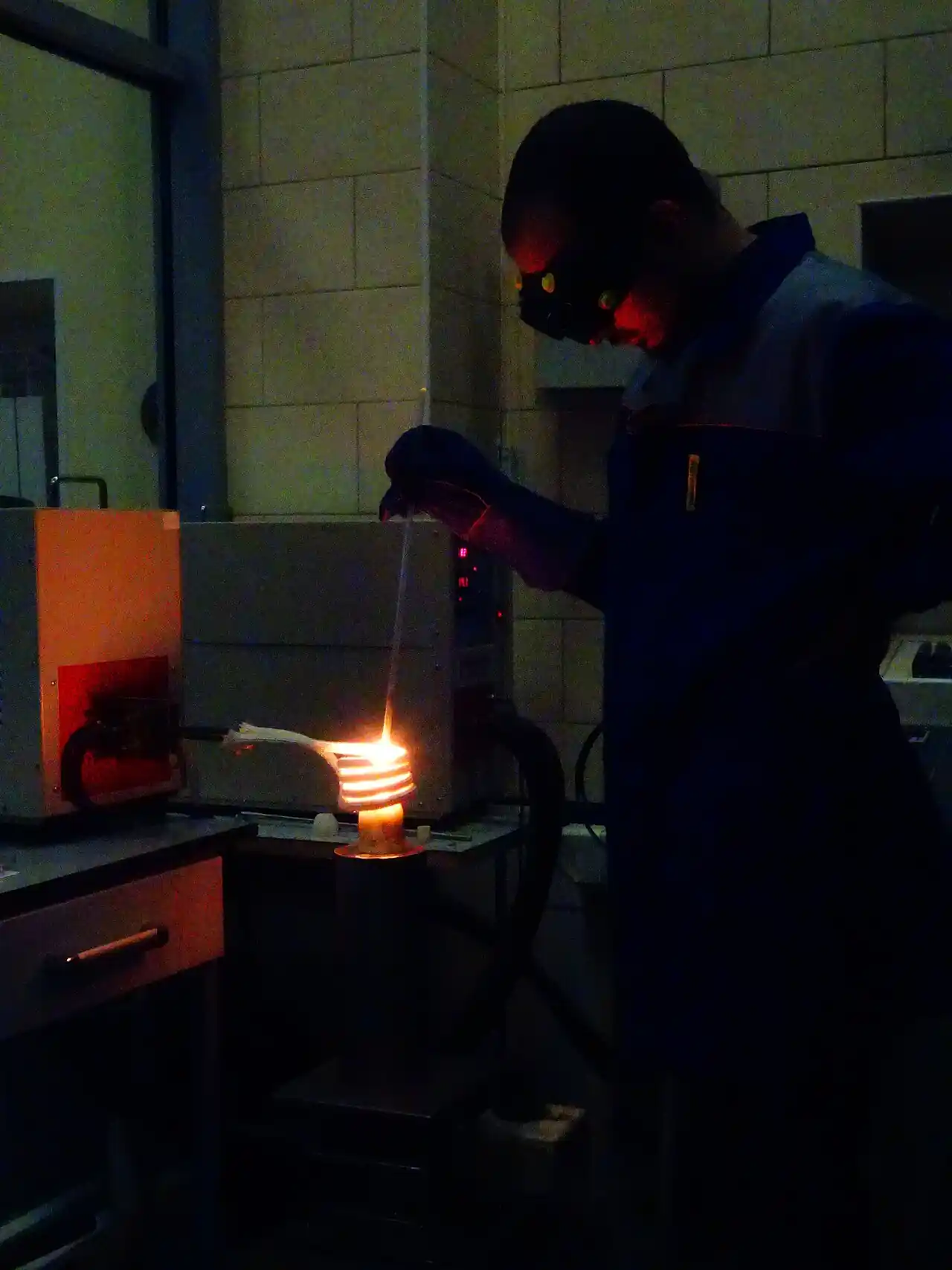
An induction furnace is a transformer whose secondary is the metal charge. A water-cooled copper coil surrounds a refractory crucible; alternating current in the coil induces eddy currents in any conductive charge inside; the charge heats by its own electrical resistance. Power flows without any electrode or flame touching the metal, and the same coil field produces electromagnetic stirring that circulates the bath, homogenizing temperature and chemistry. Stirring intensity is inversely related to frequency: line-frequency units stir hardest, high medium-frequency units stir gently. Because nothing but the refractory and, in some practices, the lining contacts the melt, the route is inherently clean for chemistry.
Frequency classes map to duty. Channel-type units run at 50 to 60 Hz line frequency with a loop of molten metal as the secondary; they hold and meter rather than melt cold charge, and their linings run months of continuous service. Coreless units, the foundry workhorses, run the medium-frequency band, roughly 150 Hz to 10 kHz, from thyristor or IGBT power supplies that rectify line power and invert it at the furnace. A coreless furnace is in effect a batch crucible furnace: the whole charge melts, taps, and the next heat can be a different alloy after a simple back-charge practice, because the crucible empties. Small precision crucibles reach the top of the band, where 10 kHz class operation concentrates power into a few kilograms; big iron melters sit near the bottom of the band, where hundreds of kilowatts per ton of charge are routine.
Energy performance of induction melting is well bounded. Melting iron from cold charge to a 1450 to 1550 C tap class, including superheat and thermal losses, commonly runs 500 to 700 kWh per ton on healthy coreless equipment, with the low end requiring good charge density, hot topping practice, and lids. Melting rate follows directly: at 600 kWh per ton, a 1 MW supply melts about 1.6 tons per hour; a shop needing 8 tons per hour needs roughly 5 MW of installed melt power plus margin. Melt losses on clean charge are commonly 1 to 3 percent, a real cost line the arc route cannot always match on oxidizing scrap.
The electric arc furnace melts by radiation. Three graphite electrodes (one electrode in the DC variant) descend through the roof; arcs strike between electrode tips and the scrap charge; the arc column, at several thousand C, radiates onto the scrap, which melts in stages as the electrodes bore down. Modern practice wraps the melt in foamy slag that shields the arcs, improves energy transfer to the bath, and protects the sidewalls; oxygen lances and wall-mounted oxy-fuel burners assist melting of cold spots; carbon injection feeds the slag foam. The furnace taps through a spout or eccentric bottom tap into a ladle. Melting is violent, loud, and dusty, and it wants a fully engineered off-gas system from day one.
Arc energy numbers are published with more bases than induction numbers, so pin the basis down. Electric energy for EAF steel melting commonly lands near 360 to 550 kWh per ton of electricity before oxygen and burner credits, with the low end belonging to large furnaces running continuous or finger-shaft charging with scrap preheat and the high end to smaller, batch-charged, cooler-scrap practice. Oxygen inputs of 20 to 40 Nm3 per ton and burner fuel add chemical energy that offsets electricity; total specific energy is therefore only comparable when the basis is stated. Electrode consumption, the signature consumable, runs roughly 1 to 3 kg per ton on modern AC practice, with DC furnaces toward the low end and older practice at 4 to 6 kg per ton; price the electrodes per ton of steel, not per furnace, because graphite is a traded commodity.
The electrical signatures differ in kind, not just degree. An induction power supply draws near-unity displacement power factor with harmonics from its rectifier front end; a 6-pulse supply needs harmonic filtering or a 12-pulse or active-front-end configuration to meet limits such as IEEE 519 at the point of common coupling. The arc furnace is the classic flicker source: arc impedance varies stochastically every cycle, and on a weak grid the voltage flicker at neighboring connections exceeds planning limits unless static var compensators or similar systems are installed. This is why Chapter 5 makes grid strength an early gate, not a late addendum.
Chemistry control splits along the contact boundary. Induction adds nothing to the melt: no electrode carbon, no combustion products, minimal slag-metal reaction beyond what the charge brings. Arc practice transfers graphite and slag chemistry into the bath deliberately, carburizing and dephosphorizing and decarburizing by slag and oxygen control, and electrode carbon pickup is a live constraint when the program calls for low-carbon or clean chromium grades. Conversely, the arc route tolerates and even wants dirty, oily, mixed scrap that would fume, bridge, or slag out an induction crucible. The routes are complementary chemically, which is exactly why the alloy list is the first selection gate.
Attribute
Induction melting
Electric arc melting
Heating mechanism
Eddy currents induced in the charge
Radiation from graphite arcs onto scrap
Power electronics
Rectifier plus inverter, 150 Hz to 10 kHz coreless, 50 to 60 Hz channel
Arc furnace transformer, AC three-electrode or DC single-electrode
Typical electric energy, labeled basis
500 to 700 kWh per ton, cold iron charge to 1450 to 1550 C tap
360 to 550 kWh per ton electricity for EAF steel before oxygen and burner credits
Signature consumable
Refractory lining and coil grout
Graphite electrodes, 1 to 3 kg per ton modern AC practice
Alloy change practice
Empty crucible each heat, change alloy per heat
Campaign practice; chemistry carries over in hot heel and slag
Scrap tolerance
Clean, dense, dry charge preferred; oily scrap fumes and bridges
Tolerates oily, mixed, dirty scrap with proper off-gas
Melt loss on charge
Commonly 1 to 3 percent on clean charge
Higher on oxidizing scrap; recovered partly in slag practice
Electrical signature
Rectifier harmonics, filterable per IEEE 519
Stochastic flicker source, SVC or STATCOM on weak grids
Noise zone
About 70 to 90 dB(A) hum at the platform
Above 100 dB(A) at the arc, enclosures and remote operation
Chapter 3 / 06
Furnace Types and Duty Boundaries
Induction splits first by core. The coreless induction furnace, a refractory crucible inside the coil, is the batch melter: charge, melt, tap, recharge, with the crucible emptied between heats. It is the default for jobbing and multi-alloy foundries precisely because nothing persists from heat to heat except the lining. The channel induction furnace runs molten metal through a closed induction loop below the bath; it excels at holding and superheating rather than cold melting, runs at line frequency with excellent efficiency in that duty, and finds its work feeding continuous casters and large pouring lines where its lining life, commonly months of continuous service, pays off.
Within coreless, size classes carry duty boundaries. Small precision crucibles of a few hundred kilograms serve investment casting and research melts where chemistry segregation cannot be tolerated. Mid-size coreless units, 1 to 10 tons per heat with 500 to 4000 kW class supplies, are the volume backbone of independent foundries. Large coreless iron melters, 10 to 30 plus tons with multi-megawatt supplies, typically run duplexed against a holding furnace so melting power is decoupled from pouring demand. Above that class, induction capital and grid demands grow faster than the alloy-flexibility benefit, and single-alloy tonnage starts pointing at the arc route.
The electric arc furnace family splits by current and by duty. AC furnaces with three electrodes dominate foundry and mini-mill steel; DC furnaces with a single electrode and bottom anode reduce electrode consumption and flicker but add bottom anode maintenance. Small EAFs of roughly 5 to 15 tons exist for foundry steel, but the economics of electrodes, off-gas systems, and cranage bite hardest at small scale, so most arc installations live at 20 tons per heat and above with single-alloy campaigns measured in weeks. The EAF is a bulk chemistry engine: it decarburizes, refines with slag, and melts anything metallic the crane can land in the basket.
Duty boundaries are sharpest in chemistry. The arc route adds carbon from electrodes and from practice, and it refines through slag-metal reactions; that is exactly right for carbon and low-alloy steel from mixed scrap, and exactly wrong for a tight low-carbon or clean chromium program unless the shop adds secondary refining such as argon oxygen decarburization downstream. The induction route cannot decarburize meaningfully; it holds the charge chemistry it is given, so the charge must be right. A shop whose value is tight chemistry on many alloys buys induction plus a good spectrometer; a shop whose value is tons of standard steel from cheap scrap buys the arc and refines on purpose.
Scrap quality is the second boundary. Induction wants dense, dry, known-chemistry charge: heavy pig, clean returns, bundled stock; oily turnings fume, wet scrap is a steam-explosion hazard in any furnace but especially in a crucible with a lid, and bulky scrap bridges above the coil until it collapses unpredictably. The arc furnace shrugs at oil and dirt because the off-gas system handles the combustion products and the slag takes the dirt, and bucket charging compacts bulky scrap mechanically. If your scrap stream is bought mixed shredded material, the arc route or heavy charge preparation is not optional; charge preparation for induction is a real cost line.
Site boundaries finish the map. Noise: the EAF arc zone runs above 100 dB(A), which forces enclosure, remote operation, and hearing conservation programs; induction platforms sit in the 70 to 90 dB(A) class, still regulated but conventionally manageable. Grid: on a weak rural service, arc flicker may cap the furnace size below your melt plan unless compensators are budgeted; induction harmonic limits are usually solvable with pulse-count and filter choices at lower cost. Emissions: the EAF baghouse and off-gas train are major capital; induction fume is smaller and mostly charging dust. Space and cranage: EAF shops need charging baskets, electrode handling, and ladle circulation; induction cells are denser. Every one of these lines belongs in the RFQ so the vendor quotes the full cell, not the bare furnace.
Downstream equipment often decides the melt interface more than the melter does. A die casting cell pulls aluminum continuously from a holding furnace at the machine; the melting furnace upstream runs flat out off-peak and the holder buffers, and aluminum machines are cold chamber machines because molten aluminum attacks steel delivery components, so the holder meters into the shot sleeve rather than dipping. Iron foundries pour from ladles or holders onto pouring lines; a steel shop taps the EAF into a casting ladle that carries the heat to tilt-pour molds, with ladle preheat and refractory as standing cost lines. The melt duty question ends at the pouring interface: specify it, and the furnace choice narrows itself.
Melt duty
Better fit
Boundary reason
Jobbing foundry, 5 to 20 alloys per week, 0.5 to 5 t heats
Coreless induction
Alloy change every heat; empty crucible; tight chemistry inheritance
Single-alloy steel, 30 t heats, 300+ t per day
Electric arc furnace
Electrode and energy economics at scale; campaign practice
Continuous caster, hold and superheat duty
Channel induction holding
Line-frequency efficiency; lining campaigns of months
Dirty, oily, mixed bought scrap
Arc route or prepared charge
Off-gas handles combustion; slag carries dirt; induction bridges and fumes
Arc flicker needs SVC or STATCOM; induction harmonics cheaper to fix
Noise-sensitive site boundary
Induction
EAF arc zone above 100 dB(A) requires enclosures
Aluminum die casting cell supply
Central melt plus machine-side holding furnace
Cold chamber machine pulls metered shots from a buffered holder
Chapter 4 / 06
Key Specification Parameters Decoded
Melt equipment datasheets are short because the real specification lives in the guarantees behind the numbers. The decode table below lists the lines that decide selection, the spread you should expect across serious quotations, and the question each line must answer. Ranges are catalog classes for foundry-scale iron and steel practice; your alloy, altitude, water system, and tariff move every row, which is exactly why the basis column matters more than the number column.
Parameter
Typical range or basis
What it controls
How to read the datasheet line
Rated power
500 kW to 12 MW class coreless; 5 to 40 MW class small-to-large EAF
Instantaneous melt capability and grid demand
Confirm continuous rating at your coolant temperature and altitude, not nameplate
Furnace capacity
0.1 to 30 t coreless; 5 to 100+ t EAF
Heat size and alloy change granularity
Distinguish crucible or shell volume from working capacity with heel
Power density
300 to 800 kW per ton of charge, coreless iron practice; small crucibles higher
Melt speed per heat and stirring violence
Too high refractory wear, too low long oxidizing heats
Melting rate
Rated power divided by specific energy, about 1.6 t per h per MW at 600 kWh per ton
Delivered tons per shift
Demand it as a guaranteed t per h on YOUR charge mix and tap temperature
Specific energy
500 to 700 kWh per ton induction iron; 360 to 550 kWh per ton EAF electricity, stated basis
Largest single operating cost
Pin the basis: charge temperature, tap temperature, hot topping, preheat credits
Tap-to-tap time
45 to 90 min small induction; 40 to 70 min modern EAF
Cycle planning with the casting line
Ask whether it includes charging, testing, and pouring delays
Electrode consumption
1 to 3 kg per ton modern AC, toward 1 DC, 4 to 6 older practice
Signature EAF consumable cost
Tie to a graphite price scenario, not a single quote
Cooling water demand
Coil circuit heat removal commonly 20 to 30 percent of rated power; closed loop with plate heat exchanger
Utilities sizing and downtime risk
Ask for flow, inlet temperature, and quality limits, plus the trip logic
Refractory campaign
150 to 400 heats silica coreless iron; 30 to 120 heats steel linings; EAF sidewalls 100 to 500 heats with patching
Lining labor, materials, availability
Demand campaigns on your alloy and temperature, with sintering support included
Rated power deserves the first decode. A furnace is sold at a nameplate the vendor measured under reference coolant and ambient conditions; at 40 C cooling water or high altitude the same unit derates. Write your worst-case utility conditions into the RFQ and demand the guaranteed rate there. The companion line, power density, is where enthusiastic quotations hide refractory pain: pushing well past the 800 kW per ton class on coreless iron shortens lining campaigns and raises melt loss, so the operating-cost table, not the melt-rate brochure, is the place to check it.
Specific energy is the line most often quoted on incompatible bases. An induction figure measured on dense pig with lids and hot topping is not comparable to one measured on bulky returns; an EAF electricity figure without stating oxygen, burner, and scrap preheat credits says almost nothing. The honest RFQ move is to specify your charge mix, charge temperature, and tap temperature, and require the energy guarantee on that basis with a test protocol at commissioning. Vendors who will not commit to a basis are telling you the number is decorative.
Tap-to-tap time must include the dead time or it is useless for scheduling: charging, sampling and spectrometer turnaround, temperature checks, slag-off, and pour all live inside the cycle. Ask for the cycle broken into stages with the assumed delays, and rebuild it against your lab's real 3 to 5 minute sample turnaround. The same discipline applies to melting rate: convert the guaranteed kWh per ton and rated power into tons per shift, then subtract your own availability factor before promising metal to the molding line.
Consumables decode into cost per ton, never per unit. Electrodes at 1 to 3 kg per ton multiply by graphite market price, and the correct RFQ line is the consumption guarantee in kg per ton on your practice, not the electrode diameter. Refractory decode similarly: campaigns in heats on your alloy, lining material cost per campaign, labor hours per relining, and sintering downtime per campaign. A cheap furnace with 90-heat linings can cost more per ton than an expensive one with 350-heat campaigns; only the per-ton table reveals it.
Cooling water is the utility line that stops shops. The induction coil circuit rejects a large fraction of rated power as heat and wants a closed loop with a plate heat exchanger, disciplined glycol or treated water chemistry, and leak detection interlocks; the EAF adds cooled panels and electrode arms with their own trip logic. Demand the flow and temperature rise at rated power, the water quality limits, and, critically, what the furnace does on cooling failure: the answer must include automatic power dump before anything dry-running cooks. Chapter 6 returns to the safety side of the same systems.
Chapter 5 / 06
Selection Decision Factors and Cost of Ownership
Run the decision in this order. Each step can end the analysis, and skipping steps is how shops end up with a furnace that melts the wrong metal for their business.
List the alloy program with chemistry bands. Count distinct chemistries per week and flag every low-carbon, clean-chromium, or segregation-sensitive grade. Many tight chemistries on small heats points at coreless induction; one or two carbon-steel families in long campaigns points at the arc route with refining downstream.
Fix the tonnage and heat size. Annual tons, tons per day, and the largest single heat the casting line can absorb. Below roughly 10 to 15 t heats with multi-alloy demand, arc capital and consumables rarely pay; above roughly 20 to 30 t single-alloy heats, induction capital and grid charges stop being gentle.
Characterize the scrap stream honestly. Chemistry spread, oil and dirt content, bulk density, and moisture control. Oily mixed bought scrap argues for the arc route or for a charge preparation line in front of induction; clean internal returns and pig argue for induction melt losses of 1 to 3 percent.
Check the electrical service before falling in love with a furnace. Available fault level and connection strength decide whether arc flicker is even permittable at your size, and harmonic limits per IEEE 519 or the local equivalent decide the induction front-end configuration. A grid study costs little and prevents the classic error of buying megawatts the connection cannot deliver.
Price the consumables per ton on a scenario, not a snapshot. Electrodes at 1 to 3 kg per ton against graphite market scenarios, refractory campaigns against your alloy, power at your tariff including demand charges, oxygen at 20 to 40 Nm3 per ton for the arc route. The per-ton table is the actual decision document.
Map the permitting envelope early. Dust collection and baghouse scope, noise at the boundary against the arc route's above-100 dB(A) zones, and flicker complaints from neighbors are permit items, and permit timelines dominate project schedules more often than furnace delivery does.
Design the cell around the melt, not the furnace alone. Charging, alloying and spectrometer loop, degassing or treatment station for aluminum programs, holding and pouring interface, ladle or holder preheat, and Cranage. The furnace is the core of the cell, but the cell is what you pay for.
Choose the commercial structure deliberately: performance guarantees on energy per ton and melt rate at your conditions, commissioning tests witnessed, refractory campaign support, and spares for the power supply. Chapter 6 gives the acceptance checklist these guarantees attach to.
The cost table below compares the two routes on the same work: a mid-size multi-alloy iron and steel program where both are physically workable. Classes are indicative for budget framing, and the specific numbers to trust are the ones your quotations bind in guarantees.
Cost element
Induction line
Arc furnace line
Notes for the comparison
Furnace and power supply, capex class
Coreless cell with supply and utilities, 0.5 to 5 MW class installs
Furnace, transformer, electrode gear, off-gas and baghouse
Arc scope includes emissions train the induction cell does not need
Electrical works class
Filters or 12-pulse front end for IEEE 519
Flicker compensation SVC or STATCOM on weak grids
Grid study decides both lines; budget it before committing
Energy per ton, labeled basis
500 to 700 kWh per ton, cold iron to 1450 to 1550 C
360 to 550 kWh per ton electricity, EAF steel, stated basis
Compare at your tariff including demand charges and off-peak spread
Consumables per ton
Lining materials, alloy additions, melt loss 1 to 3 percent
Electrodes 1 to 3 kg per ton, oxygen 20 to 40 Nm3 per ton, fluxes
Graphite price scenarios swing the arc line hardest
Refractory and lining labor
150 to 400 heats iron linings, 30 to 120 steel, relines scheduled
Sidewalls 100 to 500 heats with gunning between majors
Per-ton lining cost, not campaign length, is the comparable number
Labor per shift
One melter plus charger per cell class, spectrometer loop
Larger crew for charging, electrodes, slag, off-gas
Arc crews and cranage are standing costs
Permitting and abatement
Charging fume collection, 70 to 90 dB(A) platform
Baghouse, canopy, enclosures for above 100 dB(A) arc zones
Permit schedule often gates the project, not the delivery
Dual-melt configurations deserve their own arithmetic. A common evolution keeps coreless induction for chemistry-critical alloys and adds arc capacity for bulk grades, or runs arc melting into induction or channel holders for pouring. Duplexing spreads capital across duties instead of forcing one furnace to do both, and it is usually the right answer when the alloy list and the tonnage list point in different directions. The RFQ should be written so vendors can quote duplex options without redefining scope.
Write these inputs into the RFQ so quotations are comparable:
Alloy list with chemistry bands, the count of alloys per week, and any low-carbon or clean-chromium constraints.
Annual tons, tons per day, heat size range, and the casting line's pull pattern including peak hours.
Charge mix by percentage with chemistry spread, bulk density, oil and moisture classes, and the preparation equipment available.
Tap and pouring temperatures per alloy, and the treatment steps the metal passes through after the furnace.
Site electrical service: available power, fault level, tariff with demand charges, harmonic and flicker limits at the point of common coupling.
Cooling water availability and quality class, and the summer design temperature for the heat exchanger.
Emissions, noise, and dust permit limits at the boundary, and the permitting authority's timeline.
Guarantees demanded: specific energy on your basis, melt rate at your conditions, electrode consumption per ton for the arc route, refractory campaigns on your alloy, and witnessed commissioning tests.
Scope boundaries: charging gear, holding furnace or casting ladle interface, spectrometer loop, spares, training, and lining support.
Chapter 6 / 06
Field Practice: Lining, Charge Control, Energy, Safety
Refractory practice is the largest controllable cost line after energy. Coreless iron linings of dry vibratable silica are sintered in place on a controlled first-heat curve; steel programs move to magnesia or alumina linings with shorter campaigns; every relining is scheduled downtime, so shops run relining frames, backup crucibles, or dual cells to protect the casting schedule. The discipline that pays: follow the sintering curve exactly, dry new patch material fully, log every campaign by heat count and end-of-campaign wear measurement, and retire linings on data rather than failure. EAF practice is continuous: gunite and patch sidewalls between heats, watch hot spots with shell thermography, and plan major hearth work in campaigns.
Chemistry control is a loop, not an instrument. Sample each heat with a chilled or pin sample, analyze by optical emission spectrometry, and return the result to the melter inside 3 to 5 minutes; that turnaround is what makes small induction heats on many alloys economical. For aluminum programs, the loop extends through melt treatment: a rotary degassing unit with nitrogen or argon reduces dissolved hydrogen toward the 0.10 to 0.20 ml per 100 g class and strips inclusions, and die casting shops verify with a reduced-pressure density test before releasing metal to the holder. Skip the treatment step and porosity scrap surfaces downstream at the machining line, where it costs ten times what it costs at the furnace.
Holding and pouring practice decides how much melt quality survives to the mold. Holders run closed and temperature-controlled to stop gas pickup and slag growth; ladles and launders are preheated before first metal, with a casting ladle preheated to several hundred C so the first heat does not chill or thermally shock its lining; slag is skimmed or dams are used at the tap so slag does not ride into the pour. Tap temperatures should be the lowest the metallurgy allows: every extra 10 C of superheat is energy and lining life burned for nothing, and induction's tight temperature control is one of its quiet economic advantages over routes that overshoot and wait.
Energy management in practice is submetering plus scheduling. Meter each furnace's kWh per ton by heat and trend it; rising specific energy on induction usually means charge bulk density collapsed or lids stopped being used, while on the arc route it signals electrode or slag practice drift. Where the tariff rewards it, melt off-peak into holders and pour on demand; where the grid constrains it, stagger furnace starts to avoid coincident demand peaks. Waste heat is the remaining frontier: EAF off-gas and scrap preheat systems claw back tens of kWh per ton on the electricity line, and compressor and cooling heat can feed other plant needs. Treat the plant's energy budget as one system, because the melt shop's upgrade competes for the same transformer capacity as the heat treatment furnace row and the machine shop's new lines.
Safety discipline in melt shops is absolute because the hazard is molten metal meeting water. Exclusion: no water, no damp tools, no wet clothing, no roof leaks over melt or pour paths; cooling circuits are interlocked so a coil leak dumps power before metal can meet water. Charge control: wet or sealed scrap is rejected at the dock, full stop, because a sealed container is a steam bomb. Induction cells add coil earth-leak and ground-fault monitoring with periodic proof tests; arc floors add cooled-panel leak alarms and strict electrode and roof handling procedures. PPE, training, drills, and an audited ladle and crane maintenance program are the standing layer under all of it. Vendors support this with interlock logic and risk documents; demand them in the RFQ and audit them at commissioning.
Acceptance and commissioning close the purchase. Witness the specific energy test on your declared charge basis, the melt rate test at your coolant temperature, the cooling system performance at summer design conditions, and for the arc route an electrode consumption check over an agreed tonnage. Verify interlock behavior by supervised test, not by reading the manual: cooling failure, earth leak, and over-temperature must all dump power safely. Collect the guarantee documentation, the sintering and first-heat procedures, the spares list with real lead times, and the training records. Then keep the plant's own verification running: daily kWh per ton trending, per-campaign refractory records, monthly interlock proof tests, and a quarterly audit of the exclusion zones. The shops that treat melt equipment as a system to be verified are the shops where the five-year cost table lands where the capital request said it would.
FAQ
Which furnace suits a small jobbing foundry running many alloys?
A coreless induction furnace, almost always. The crucible empties each heat, so alloy changes cost one back-charge instead of a campaign change, melt loss on clean charge runs 1 to 3 percent, and the melter holds chemistry tightly with a fast spectrometer loop. Arc economics need single-alloy tonnage, off-gas capital, and electrode logistics that a small multi-alloy shop cannot spread across its volume.
How do I compare energy cost per ton between induction and EAF fairly?
Fix the basis first. Induction iron melting commonly runs 500 to 700 kWh per ton from cold charge to a 1450 to 1550 C tap; EAF steel electricity commonly runs 360 to 550 kWh per ton before oxygen and burner credits, and oxygen at 20 to 40 Nm3 per ton plus burner fuel are energy too. Then apply your tariff with demand charges. Quotations without a stated charge and tap basis are not comparable numbers.
Can an EAF run clean chromium alloys given electrode carbon pickup?
It can, but it fights its own physics. Electrodes and practice add carbon, so low-carbon stainless work on the arc route runs with flat bath control, foamy slag discipline, and usually argon oxygen decarburization downstream, which is the standard mill pattern. If the program is many small clean-chromium heats, coreless induction inherits charge chemistry cleanly and skips that fight entirely.
What are the grid implications: flicker and harmonics?
The arc furnace is a stochastic flicker source; on a weak connection its voltage fluctuations exceed planning limits unless static var compensation or a similar system is budgeted, so commission a grid study before selecting size. Induction supplies bring rectifier harmonics instead, solved with 12-pulse or active front ends and filters to meet limits such as IEEE 519 at the point of common coupling, generally at lower cost than flicker compensation.
What share of operating cost do electrodes and consumables take?
On the arc route, electrodes at 1 to 3 kg per ton are the signature line and swing with graphite markets, commonly landing as a mid-single-digit to low-double-digit percentage of conversion cost per ton depending on practice and price cycle; oxygen, fluxes, and refractory add more. Induction replaces that line with lining materials and relining labor at 30 to 400 heats per campaign depending on alloy. Model both as cost per ton under price scenarios.
What noise and emissions permitting issues should I expect?
The EAF arc zone runs above 100 dB(A), so expect enclosure requirements, remote operation, hearing conservation programs, and boundary noise limits in the permit, plus a baghouse and off-gas train for dust. An induction platform sits around 70 to 90 dB(A) with mainly charging fume to collect, a materially lighter permitting package. Permit timelines frequently gate the project schedule, so file early.
Can a retrofit shop run both furnace types together?
Yes, and dual-melt shops often should. Keep coreless induction for chemistry-critical and small heats, add arc capacity for bulk single-alloy tonnage, and duplex through induction or channel holders that buffer pouring. The same logic answers growth: when tonnage and alloy-count point in different directions, split the duty across two furnaces rather than forcing one machine to do both badly.