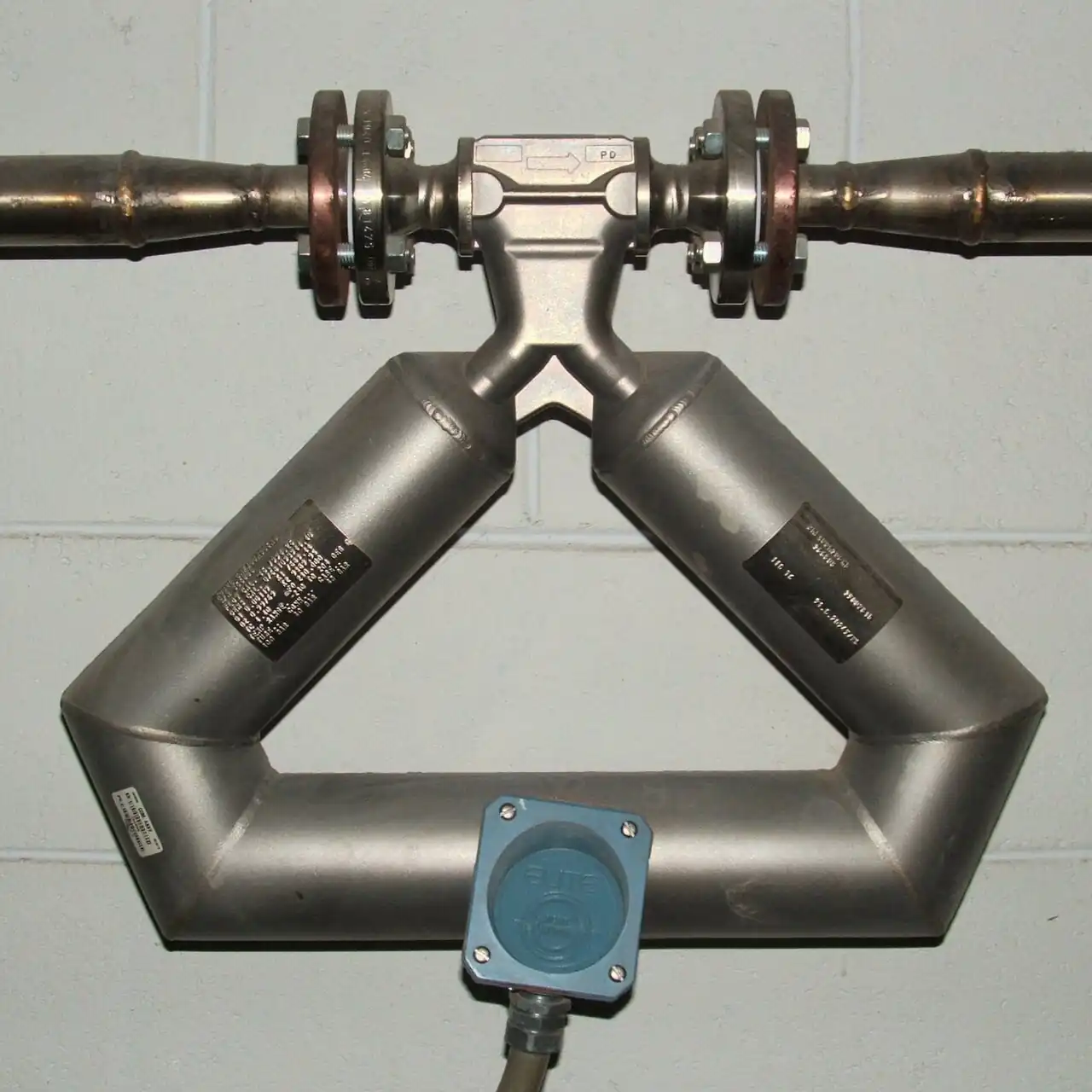
An inline viscometer is an instrument mounted directly in the pipe, spool, or vessel that reports fluid viscosity continuously, classically as a 4 to 20 mA signal with HART or Modbus riding the same pair, and frequently sold under the names process viscometer or viscosity transmitter. Where the laboratory rotational viscometer dips a spindle into a 600 mL beaker and yields one number per sample, the inline unit produces a reading every few seconds at full process temperature and pressure without an operator. Four sensing families carry nearly all industrial duty: vibrating element probes in tuning fork or rod form, torsional oscillating piston and sphere probes, capillary side stream systems, and rotational process spindles in sealed tees. Together they span roughly 0.1 to 100,000 millipascal seconds by model family, with accuracy of 1 to 2 percent of reading on Newtonian fluids after calibration against certified standards.
Procurement engineers meet these instruments where viscosity itself is the control variable: polymer and resin reactor end point, where viscosity climbs with conversion; heavy fuel oil blending, where the burner wants 15 to 25 centistokes at the tip; printing ink and coating dosing; sauce and dairy standardization; lubricant and asphalt blending; and polymer dosing in water treatment at 0.5 to 2 percent solution strength. The decision this page settles is which sensing principle matches the fluid, Newtonian or otherwise; which installation geometry keeps the probe wet, clean, and gas free; what compensation converts the raw reading to a reference temperature; and what calibration evidence makes the number defensible. The answer lands as an RFQ line set: sensing principle and wetted materials, viscosity range and accuracy, shear rate statement, temperature compensation basis, installation geometry, and the certificates demanded at handover.
This page treats the inline viscometer as a purchasing object: the damping and shear physics behind each sensing family, the honest accuracy and span classes, what shear rate means for non-Newtonian fluids, how temperature compensation and traceable calibration keep the number defensible, and how all of it converts into RFQ language. It is written for engineers who issue purchase specifications and acceptance criteria, not for readers who want a brochure summary.
Chapter 1 / 06
What an Inline Viscometer Is and What Is Being Decided
The defining property of a process viscosity meter is that it stays. A laboratory instrument sees the fluid after it has cooled, degassed, and usually waited in a bottle; an inline viscometer sees the fluid as the process sees it, at temperature, at pressure, in motion, and continuously. That single difference explains both the value and the difficulty of the purchase. The value is control: a reactor endpoint, a blend ratio, or a burner viscosity can be trimmed in seconds instead of waiting on a shift laboratory. The difficulty is that the instrument must survive and stay honest in conditions the beaker never sees, including velocity past the sensor, entrained gas, coating products, and temperatures where viscosity moves several percent for every degree.
What is being decided in this purchase is four commitments at once. First, the sensing commitment: vibrating element, torsional probe, capillary loop, or rotational spindle, each with a different span, shear rate behavior, and maintenance story. Second, the installation commitment: a wetted probe in a DN 50 or larger tee, a flanged spool, a tank nozzle, or a pumped side stream, each with different isolation and serviceability. Third, the compensation commitment: whether the instrument reports viscosity at line temperature, or converts to a reference such as 40 or 100 deg C using an internal curve family or a user table, and whose temperature input the conversion believes. Fourth, the verification commitment: which certified standards, which intervals, and which laboratory method arbitrates when the inline number and the shift check disagree. A quotation that answers only the first of these is a probe price, not a measurement.
The accuracy expectations should be fixed before the technology is chosen, because the families overlap less than catalogs imply. On Newtonian reference fluids, a well calibrated vibrating element or torsional probe holds 1 to 2 percent of reading, with repeatability around 0.5 percent of reading on the established families; a capillary loop with steady flow control and a good differential measurement holds similar class; a rotational process spindle holds 2 to 5 percent depending on seal friction and shear rate discipline. Against those numbers the process itself moves: mineral oils change viscosity by roughly 2 to 10 percent per deg C depending on grade, polymer melts far more, and heavy fuel oil near the burner tip roughly doubles or halves within a 20 deg C band. The instrument is therefore never bought alone; it is bought with a temperature measurement, because without one the reading is a snapshot of an unstated condition.
The instrument also lives among companions on the same skid and the same conduit, and the RFQ should name them. Temperature arrives either from the integral RTD PT100 element built into the probe or from an external temperature transmitter on the line whose value the viscosity converter consumes. A pressure transmitter on the loop confirms that the side stream is flowing and the line is liquid full. A densitometer answers mass per volume where the product density is itself a control variable, and where mass flow is already being bought a coriolis flowmeter on the same line can report density as a native second variable, which reshapes the purchase the moment flow enters the requirement. The analytical neighbors answer different questions: a conductivity meter and a pH meter cover ionic aqueous chemistry, a turbidity meter reads suspended solids, a dissolved oxygen meter owns fermentation state, a moisture analyzer covers water content in solids, and a spectrophotometer in the laboratory resolves species that bulk properties cannot. Each companion has its own leaf in this encyclopedia; this page covers the viscosity instrument itself.
Compressed to one sentence, the decision is whether continuous, compensated, traceable viscosity at a stated shear rate and accuracy is bought as a system, probe plus geometry plus compensation plus verification regime, or as a transmitter part number threaded into the nearest tee. The chapters that follow supply the physics, the hardware families, the datasheet rows, the selection logic, and the failure modes needed to write it the first way.
Chapter 2 / 06
How Vibrating, Torsional, and Capillary Viscosity Measurement Work
The vibrating element family is the volume product, and one line of physics explains it. A tuning fork or rod, driven at its natural frequency in the hundreds of hertz, moves through the process fluid; the fluid resists that motion viscously, and the oscillator loses energy in proportion. The drive electronics hold the amplitude constant and measure the extra power required to do so, and that power, mapped through a factory calibration, is the dynamic viscosity. Because the same fluid mass also loads the resonator and lowers its frequency, the probe reads density from the frequency shift in the same breath, and the pair of results yields kinematic viscosity, centistokes, as dynamic viscosity divided by density. A modern vibrating probe therefore reports three live values: dynamic viscosity, density, and temperature from the onboard RTD PT100 element, all in a single penetration of the line.
The damping mechanism deserves the respect of one more paragraph, because it sets the honest limits. For a Newtonian fluid, the shear stress on the oscillating surface is proportional to viscosity times the velocity gradient near the surface, and the calibration transfers cleanly between fluids of the same class. At the top of a family's span the flow field around the probe stiffens, sensitivity flattens, and makers publish a maximum viscosity at which the stated accuracy no longer holds; above it the reading becomes an indication, not a measurement. Entrained gas breaks the calibration in the other direction, inflating apparent damping erratically rather than predictably, which is why mounting geometry and gas exclusion dominate chapter 6. A coating works as added mass and added damping, drifting the reading slowly until it freezes at a nonsense value; the practical defense is a scheduled verification against a known standard and a cleaning regime matched to the product.
Torsional probes rotate the same idea about an axis. An oscillating piston, sphere, or cylinder shears the fluid through a thin annular film at hundreds of cycles per second, and the torsional energy loss maps to viscosity the same way fork damping does, with the advantages of a compact insertion body and very small displaced volume. The shear rate is high and fixed by geometry, typically hundreds to thousands of reciprocal seconds, which is intrinsic to the design: it suits Newtonian oils, resins, and syrups, and it must be stated when the fluid is not Newtonian, because a pseudoplastic product read at high shear reports a lower viscosity than the same product read in the laboratory beaker at low shear. This honesty clause, the shear rate statement, is the single most omitted line on viscometer datasheets and the one that decides whether plant and laboratory numbers will ever agree.
The capillary family is the oldest inline method and still the reference shape for heavy fuels. A continuous side stream is pumped at constant flow through a precision bore capillary; in laminar flow the pressure drop along the tube is proportional to dynamic viscosity times flow rate divided by the tube radius to the fourth power, the Hagen-Poiseuille law in words, so a constant flow plus a measured drop equals viscosity. The drop is read by a differential pressure transmitter across the capillary ends, the stream is temperature controlled or temperature compensated, and the whole loop behaves like a small extracted laboratory running in real time. The principle is identical to the glass capillary viscometer of ASTM D445, the kinematic reference method of the petroleum industry, which is exactly why refineries trust it on residue and heavy fuel oil service despite the plumbing.
Temperature compensation turns a raw reading into a controllable one. Viscosity falls steeply with temperature, 2 to 10 percent per deg C for typical mineral oils and worse for heavier cuts, and the petroleum industry formalizes the behavior in the ASTM D341 viscosity temperature charts and their Walther equation: plotting log log of kinematic viscosity against log of absolute temperature linearizes most petroleum fluids, so two reference points anchor an entire curve. Process instruments implement the same idea internally, holding a product specific curve family and reporting viscosity normalized to 40 or 100 deg C so the control loop does not chase ambient drift. The compensation input is either the integral element or an external temperature transmitter value, and the choice belongs on the datasheet because a bypass installation that lets the sample cool between line and sensor manufactures exactly the error the compensation assumes away.
What the families share is the output chain and the error budget discipline. Every family reports 4 to 20 mA with HART, Modbus RTU, or PROFIBUS PA riding the loop or bus, updates within seconds, and carries its honesty clauses: gas bubbles inflate damping on vibrating and torsional probes, coating shifts every wetted surface, erosion roughens polished elements in abrasive service, and capillary loops clog or lose flow control. The selection chapters treat each clause as a boundary, because a viscosity meter bought against its physics is not an inaccurate instrument, it is a confidently wrong one that the loop will trust until the product is out of specification.
Chapter 3 / 06
Types, Construction, and Duty Boundaries
The vibrating element family covers the broadest catalog ground. Construction is a slender 316L stainless probe, fork or rod, extending from a threaded, flanged, or hygienic process connection into the flow; drive and sense coils live in the head at ambient; an integral temperature element compensates; and the electronics converts damping and frequency into the three live outputs. Wetted variants extend to Hastelloy C for aggressive chemistry and to PTFE or PEEK sealed heads for solvents, and the established families span roughly minus 40 to 300 deg C and pressure to 200 bar by model. Insertion through a DN 50 or larger tee, a spool piece, or a tank nozzle covers most geometries, pressure loss is negligible, and the probe tolerates the 0.3 to 3 meters per second velocity band that keeps the sample fresh without exciting the resonator.
The torsional family compresses the same physics into a smaller body. An oscillating piston or sphere on a torsional tube shears the product through an annular gap, and the head converts torsional energy loss to viscosity; spans reach from light solvents into the hundreds of thousands of millipascal seconds on extended models, response is seconds, and the small insertion footprint suits tees and nozzles where a fork would crowd the pipe. The rotational process family, the direct descendant of the laboratory instrument, mounts a sealed spindle and cup assembly in a tee or spool, drives the spindle through a magnetic coupling, and measures torque at a chosen, stated shear rate; it earns its plumbing wherever the product is non-Newtonian and the control argument needs a defined shear, from polymer dosing in water treatment at 0.5 to 2 percent solution strength to ink and coating body control. ASTM D7483, the standard practice for rotational process viscometers of the piston type, governs this family's calibration discipline.
The capillary family is a system rather than a probe. A takeoff with isolation, a small pump or constant head device driving a fixed flow, a precision capillary in a temperature controlled oven or traced enclosure, a differential pressure transmitter across the capillary, and a return to the line or drain: the loop is assembled from instrument parts the plant already stocks, and a sample conditioning system in miniature keeps the stream filtered and steady. Legacy falling piston and falling ball process types persist in a few plants and earn one sentence: real, serviceable, increasingly replaced by vibrating and torsional probes with better response and fewer moving parts.
Duty boundaries keep the families honest against each other. A vibrating or torsional probe does not belong in a fast abrasive slurry, erosion changes the resonator surface and the calibration with it; that duty gets a flush mounted probe behind a baffle, a rotational design with hard coatings, or the admission that inline viscosity is the wrong measurement there. A capillary loop on a clean, hot, heavy fuel line is decades of proven practice; the same loop on a crystallizing or fouling product plugs, and the maintenance ledger decides. Gas entrainment defeats vibrating and torsional probes first, capillaries second through flow instability, and rotational spindles last but never completely. The comparison table below compresses the boundaries into the form a specification meeting can argue from.
Sensing family
Span, typical
Shear rate behavior
Best duty
Principal burden
Vibrating fork or rod
0.1 to 100,000 mPa s by model
High, fixed by resonator geometry
Newtonian oils, resins, syrups, fuels, reactives needing density too
Coating, gas bubbles, erosion of resonator surface
Torsional piston or sphere
Wide, into the 100,000 mPa s class
High, fixed, hundreds to thousands per second
Compact insertion on viscous but clean products
Same gas and coating clauses; annular gap sensitivity
Capillary side stream
2 to 2,000 cSt classic heavy fuel window
Laminar tube flow, well defined
Heavy fuel oil, residue, asphalt, heated lines
Loop plumbing, constant flow discipline, fouling
Rotational spindle in tee
Mid to high span by spindle
Chosen and stated, per ISO 3219 logic
Non-Newtonian dosing, polymer solutions, ink body
Seals and bearings, slower response, drift discipline
Falling piston or ball, legacy
Narrow by design
Gravity driven, low
Surviving installations, simple liquids
Moving parts, cycles per hour ceiling, obsolescence
Construction boundaries close the chapter. Hazardous area versions carry ATEX or IECEx certificates with the installation concept, flameproof or intrinsically safe, stated alongside the certificate rather than implied. Hygienic executions bring electropolished wetted surfaces, crevice free clamp connections, and clean in place tolerance with 3-A and EHEDG intent for food and pharmaceutical rooms. Heated constructions, jacketed heads and traced probes, hold asphalt, bitumen, and heavy fuel above their pour point so the measured viscosity belongs to the product and not to a cooling boundary layer. Every one of these lines changes the delivery time and the price by real factors, so the specification should carry them from the first issue, not as variations discovered after award.
Chapter 4 / 06
Key Specification Parameters
The datasheet rows below decide whether a quoted instrument matches the service; values are stated as the common industrial span of the established families, with every row confirmed against the model datasheet before order.
Attribute
Typical range or options
What it decides
Viscosity span
0.1 to 100,000 mPa s across families; single model spans narrower
Whether operating point and startup fluids both sit inside the calibrated window
Accuracy, Newtonian
1 to 2 percent of reading after calibration; rotational 2 to 5 percent
Credibility of the control setpoint and the blend accounting
Repeatability
About 0.5 percent of reading, vibrating and torsional families
Control stability where the reading trims a dosing loop
Process temperature
Minus 40 to 300 deg C by model; heated heads for asphalt duty
Compensation validity, seal limits, and hold-heat provisions
Process pressure
To 200 bar class by connection and family
Rating of the insertion hardware on the actual line
Wetted materials
316L standard; Hastelloy C; PTFE or PEEK seals; hygienic polish
Corrosion envelope, cleanability, and product contact compliance
Shear rate statement
Fixed high shear on resonators; selectable on rotational, ISO 3219 logic
Whether plant and laboratory numbers can ever be compared
Compensation sensor
Integral RTD PT100 class element; external temperature transmitter input options
Whose temperature the reference viscosity conversion believes
Outputs
4 to 20 mA viscosity, density, temperature; HART, Modbus RTU, PROFIBUS PA
Wiring count and where the reference conversion runs
Calibration basis
NIST traceable silicone and mineral oil standards, 10, 100, 1000 cSt class points
Traceability of the number the instrument ships believing
The calibration row deserves expansion because it separates a traceable measurement from an indicated one. Factories calibrate against certified viscosity standards, silicone and mineral oils whose values are traceable to national standards at 10, 100, and 1000 centistoke class points, and the certificate belongs with the instrument file. Field verification uses the same logic in miniature: isolate the probe or loop, check the zero condition, run a certified standard through the wetted path at controlled temperature, and compare against the certificate value. An instrument that cannot pass that check between services has no business backing a reactor endpoint, and a plant that skips the check will eventually discover that both the inline reading and the laboratory beaker have drifted, in different directions, for different reasons.
Installation parameters are datasheet rows too, not site improvisations, and the table below states the practical spans and the reasoning that connects them.
Installation parameter
Practical span
Sizing logic
Velocity past the probe
0.3 to 3 m per second, vendor band
Fast enough to keep the sample fresh, slow enough to avoid erosion and vibration coupling
Insertion geometry
DN 50 or larger tee, spool, or tank nozzle; element fully immersed
Partial immersion or wall proximity shifts damping and the reading with it
Distance from pulsation
Away from pump discharge where the line allows
Pressure pulsation and vibration couple into the resonator and bias damping
Gas management
Low point of a downward run; vents at high points; never at a pump suction vortex zone
Bubbles inflate apparent damping erratically and defeat calibration
Side stream design
Inlet and outlet isolation, filter, constant flow, short traced runs
Capillary systems live or die by steady flow and honest temperature
Verification access
Isolation valved so the probe or loop is serviceable without a line stop
Quarterly standard checks are impossible on hardware that cannot be isolated
Two further rows belong in the specification text even though they rarely appear as single cells. First, the reference temperature basis: whether the instrument reports line temperature viscosity, 40 deg C normalized viscosity, 100 deg C normalized viscosity, or another reference, and which curve family, ASTM D341 logic for petroleum products or a user polynomial, performs the conversion. Second, the companion instrumentation already on the skid: a pressure transmitter confirming liquid full operation, and the existing flow meter on the blend line whose signal the controller combines with viscosity to close the ratio loop. Where the fluid is conductive and volume matters more than mass, an electromagnetic flowmeter may already occupy the run, and the viscometer placement must respect its straight run requirements rather than compete with them. Stating both rows in the RFQ prevents the two commonest commissioning arguments: whose temperature, and whose flow.
Chapter 5 / 06
Selection Decision Factors and RFQ Language
The selection sequence runs as a checklist, and each line eliminates a class of quotations before price comparison begins.
State the control objective as a viscosity tolerance at a stated reference temperature, then convert it to a reading tolerance at line temperature before looking at instruments.
Characterize the fluid: Newtonian or not; shear thinning, thixotropic, or rheopectic behavior; chemistry against 316L, Hastelloy C, PTFE, and PEEK; solids loading; gas entrainment likelihood; pour point and the heat it demands.
Pick the sensing family against the boundaries in chapter 3: vibrating or torsional for clean Newtonian and moderately viscous duty, capillary for heated heavy fuels, rotational with a stated shear rate for non-Newtonian control.
Fix the installation: tee, spool, nozzle, or side stream, with isolation, gas geometry, and velocity inside the 0.3 to 3 meters per second band decided on the drawing.
Fix the compensation: integral element or external temperature transmitter value, reference temperature, and the curve family that performs the normalization.
Fix the calibration and verification regime: certified standard points, field check interval, and the laboratory method, ASTM D445 kinematic or an ISO 3219 style rotational procedure, that arbitrates disagreements.
Fix the integration: 4 to 20 mA plus HART or Modbus, and the dosing pumps, blend valves, or heaters the loop will drive.
Add the compliance lines: hazardous area certificate with installation concept, hygienic intent where the room demands it, material certificates for wetted parts.
Against the neighboring instruments, the inline viscometer holds specific ground, and the comparisons belong here rather than in a page title. A densitometer reads mass per volume and is silent on resistance to flow; the two correlate only through product specific tables, and a line that needs both buys both or buys one instrument that reports both, because a vibrating probe or a coriolis flowmeter natively carries density alongside viscosity or mass flow. A coriolis flowmeter on the product line delivers mass flow and density as primary variables, with viscosity available as a secondary derived output on some families, and that economy wins whenever flow is already being bought; the dedicated inline viscometer wins when viscosity accuracy, span, or shear rate statement matters more than the bonus variables. An electromagnetic flowmeter reads volume on conductive fluids and contributes nothing to viscosity, though the two share a run on many blend skids. On the analytical side, a conductivity meter and a pH meter resolve ionic aqueous chemistry, a turbidity meter resolves suspended solids, a dissolved oxygen meter resolves biological state, and a moisture analyzer resolves water in solids: each answers a different question, and a laboratory spectrophotometer resolves specific species by light absorption when the argument needs selectivity rather than speed. A flow meter of any technology closes the mass or volume balance on the blend, but only the viscometer closes the body or endpoint argument, and plants that try to infer viscosity from flow and pressure alone eventually buy the viscometer anyway.
The application map below compresses the practice into the form a project file carries.
Application
Typical construction to specify
Check before order
Polymer and resin reactor endpoint
Vibrating rod or torsional probe in a nozzle or loop reactor takeoff, 316L or Hastelloy C wetted
Span headroom above endpoint viscosity; coating and auto-wash provisions
Heavy fuel oil blending and burner control
Capillary side stream with traced and heated runs, or vibrating fork with heated head
15 to 25 cSt burner window; ASTM D341 compensation to reference temperature
Printing ink and coating dosing
Rotational process spindle with stated shear rate, or torsional probe
Shear rate statement so laboratory and line agree on non-Newtonian body
Sauce, dairy, and syrup standardization
Hygienic vibrating fork, polished clamp connection, clean in place tolerance
Coating drift schedule; certification intent for the food room
Lubricant and grease blending
Torsional or vibrating probe plus densitometer on the same skid
Grade span across the blend; certified standard points at both ends
Asphalt and bitumen quality control
Heated capillary loop or jacketed vibrating probe, 150 deg C class service
Hold-heat provisions; fouling and cleaning regime
Polymer dosing in water treatment, 0.5 to 2 percent solutions
Rotational process viscometer with low shear spindle or sidestream torsional
Shear sensitive product; do not read high shear only and call it dose strength
The RFQ block should be written once and reused: quantity and sensing family; viscosity span with the operating point and startup fluids inside it; accuracy and repeatability class on Newtonian reference fluids; shear rate statement for the actual product behavior; wetted materials and seals; process temperature and pressure at the installation point, with hold-heat requirements for heated products; installation geometry with isolation and gas management; the compensation basis, integral RTD PT100 class element or external temperature transmitter value, reference temperature, and curve family; outputs and protocol; the calibration certificate basis against NIST traceable standards and the field verification procedure; hazardous area and hygienic certificates with installation concept; and the acceptance test, a live comparison against the plant laboratory method on the actual product at two temperatures. A quotation returned without the shear rate statement or the calibration certificate basis is incomplete at any price.
Chapter 6 / 06
Installation, Standards, Failure Modes, and Maintenance
Installation geometry carries more of the accuracy than any electronics setting. The probe belongs in a DN 50 or larger tee or spool with the sensing element fully immersed and clear of the wall, in a run where velocity stays inside the 0.3 to 3 meters per second band, and away from pump discharge pulsation where the piping allows it. Mount at a low point of a downward run so that bubbles rise away from the element rather than collecting on it, and vent high points so the line can be proven liquid full. Side stream and capillary installations follow sample conditioning system logic in miniature: short traced runs so the sensor and the fluid agree thermally, a filter that protects the capillary without damping the response, isolation so the loop is serviceable without a line stop, and a check that the sample arriving at the sensor is the process fluid and not a cooled, settled, or fractionated version of it.
Commissioning earns the traceability claim. Record the factory certificate points in the instrument file, verify the zero and a certified standard through the wetted path at controlled temperature, then run the live product against the plant laboratory, an ASTM D445 kinematic capillary or an ISO 3219 style rotational procedure as the product demands, at two temperatures so the compensation slope is tested and not just the intercept. Where an external temperature transmitter feeds the compensation instead of the integral element, verify the two agree within a stated margin at two temperatures, because a compensation input that disagrees with reality manufactures error at several percent per degree. File the comparison as the acceptance test; it is the baseline every later drift argument refers to.
The standards frame assembles from several directions, honestly, because no single standard defines a process viscometer. ASTM D7483 governs the calibration and operation of rotational process viscometers of the piston type and is the correct citation for that family. ASTM D445 remains the kinematic capillary reference method against which inline capillaries and vibrating probes are cross-checked on petroleum fluids, and ASTM D341 with its Walther equation governs the viscosity temperature charts used for reference temperature normalization. ISO 3219 defines rotational rheometry discipline, shear rate statement above all, for instruments that must state their shear. Electrical safety and EMC follow IEC 61010 and IEC 61326, hazardous area versions carry ATEX or IECEx with the installation concept, and hygienic executions reference 3-A and EHEDG design intent. Citing the standards by name in the RFQ moves the burden of proof to the supplier, where it belongs.
Failure modes follow the physics. Coating and buildup on the resonator, spindle, or capillary wall drift the reading slowly and then freeze it; scheduled standard checks catch the drift, clean in place or solvent wash restores it, and heated products get auto-wash cycles designed in rather than improvised. Erosion by solids roughens the wetted surfaces and changes the calibration; the fixes are hard coatings, filtration upstream, or a protected mounting chosen before the surfaces disappear. Gas entrainment inflates apparent damping and biases vibrating and torsional probes erratically; the geometry fixes are low point mounting and venting, and the operational honesty is declaring fill and transfer periods as indicative rather than controlled. Seal failure lets process fluid into the head and usually announces itself as instability followed by silence; a pressure transmitter on the loop and routine inspection of the process seal catch it early. Electronics drift is quiet and slow, which is exactly why the quarterly certified standard check exists, and cavitation or flashing near a pump is a mounting error to be corrected, not a calibration offset to be trimmed.
Maintenance is deliberately boring. Verify against a certified standard quarterly on control-critical loops and annually on monitoring duty; clean on the schedule the product sets, with auto-wash where fouling is structural; recalibrate against traceable standards on the interval the certificate and the drift history justify; keep one spare probe or capillary assembly on the shelf for every control-critical installation, because the alternative to a spare is a loop running blind for a procurement cycle; and log every laboratory comparison so the drift history argues for or against the next interval. The throughline of this page is that an inline viscometer is a physics instrument wearing a transmitter's clothes: bought against its physics, installed with its geometry, and verified on a schedule, it holds its stated class for years, and skipped on any of the three it produces numbers that look exactly as authoritative as good ones.
FAQ
What is the difference between an inline viscometer and a lab rotational viscometer?
A laboratory rotational viscometer dips a spindle into a beaker, usually 600 mL, at bench temperature and yields one number per sample with the operator controlling everything. An inline viscometer mounts in the pipe or vessel, reads continuously at process temperature and pressure within seconds, and feeds 4 to 20 mA or a digital bus directly. The two agree only when shear rate and temperature are matched, so state both whenever the laboratory result arbitrates the inline reading.
Does a vibrating probe measure dynamic or kinematic viscosity?
Both. The damping of the oscillating fork or rod gives dynamic viscosity in millipascal seconds, and the same fluid mass shifts the resonant frequency, giving density in the same measurement. Kinematic viscosity in centistokes follows as dynamic viscosity divided by density, computed inside the transmitter. Datasheets should state which of the three values each analog output carries, because control loops and laboratory methods do not all use the same one.
How does temperature change the reading and how is it compensated?
Viscosity falls roughly 2 to 10 percent per deg C for typical mineral oils, more for heavier and polymer bearing products, so an uncompensated reading is a snapshot of an unstated condition. Instruments measure temperature with an integral RTD PT100 class element or accept an external value, then normalize to a reference such as 40 or 100 deg C using a curve family, ASTM D341 Walther logic for petroleum fluids or a user polynomial. State the reference temperature and the curve basis in the specification.
Can an inline viscometer handle non-Newtonian fluids?
Yes, with one honesty clause: viscosity must be quoted at a stated shear rate. Vibrating and torsional probes shear at a high fixed rate set by their geometry, hundreds to thousands of reciprocal seconds, so shear thinning products read lower than in a slow laboratory beaker. Rotational process spindles let you select and state the shear rate, ISO 3219 discipline, which is why polymer solutions and inks usually get rotational instruments. Anchor the control strategy to one instrument type and one shear rate.
What calibration standards should the instrument reference?
Certified viscosity standards with values traceable to national institutes, classically silicone and mineral oil fluids at 10, 100, and 1000 centistoke points, with the certificate filed at handover. Field verification runs a certified standard through the wetted path at controlled temperature and compares against the certificate value. Cross-check the live product against the plant laboratory method, ASTM D445 kinematic or a rotational procedure, at two temperatures so the compensation slope is tested too.
Where in the line should the probe be mounted?
In a DN 50 or larger tee or spool with the element fully immersed and clear of the pipe wall, in a run with velocity between 0.3 and 3 meters per second, away from pump discharge pulsation where the piping allows. Mount at a low point of a downward run so gas bubbles rise away from the sensing element, vent high points, and provide isolation so the probe can be verified without stopping the line. Capillary side streams follow the same logic with a filter and constant flow added.
What maintenance interval and failure signs apply?
Verify against a certified standard quarterly on control-critical loops, annually on monitoring duty, and clean on the schedule the product sets. The classic failure signatures are slow drift then a frozen reading from coating, erratic jumps from gas entrainment, step changes after erosion of the wetted surface, and instability from a failing process seal. Keep one spare probe or capillary assembly for every control-critical point; a blind loop is more expensive than a shelf part.