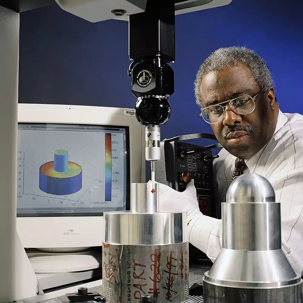
A touch-trigger probe is the discrete-point sensing head fitted to a coordinate measuring machine: the stylus tip contacts the part surface, the contact breaks an internal seat, and the machine control latches a single coordinate point. It is the default probing mode for first-article inspection, fixture setup, and feature-to-feature dimensioning on machined parts, molds, and castings.
Buying a touch-trigger probe means deciding four things: the seating mechanism (kinematic switch or strain gauge), the repeatability class the inspection tolerance actually needs, the stylus length and tip ball the part geometry allows, and the interface between probe head, CMM quill, and controller. This page decodes the datasheet lines a specifier has to write into the RFQ, from 2-sigma repeatability in microns to trigger force in grams and probe overtravel limits.
The touch-trigger probe is one branch of the CMM probing family. The scanning probe collects thousands of deflection samples per second for form evaluation, the probe changer extends reach between stylus configurations mid-program, and non-contact sensors such as a structured light scanner or an industrial camera cover flexible or delicate surfaces. Each has a duty it wins; this page is about the discrete-point branch and where it remains the right economic choice.
A touch-trigger probe turns surface contact into machine coordinates: one touch, one point, an uncertainty budget set by seating repeatability, stylus bending, and approach direction. This page explains the mechanism, the numbers that separate a shop-floor head from a laboratory head, and exactly what to demand on the datasheet before writing the purchase order.
Chapter 1 / 06
What Is a Touch-Trigger Probe
A touch-trigger probe is an electromechanical contact sensor that mounts on the spindle or quill of a CMM, on the spindle of a machining center, or on a measuring arm. Inside the housing, a stylus carried on a kinematic seat snaps out of contact when the tip touches a surface; the break generates a latch signal that freezes the machine position counters. The result is a single surface point whose uncertainty is a small, largely repeatable offset from the true stylus ball center plus the machine's own positioning error.
The selection question arises whenever a quality plan has to measure discrete geometry: bolt-hole positions on a machined flange, a bore diameter and its axis, a step height on a casting, or a fixture offset before a cut. If the plan needs thousands of points per surface to evaluate roundness or profile, a scanning probe is the better tool and the touch-trigger head only slows the cycle. If the plan needs 20 to 200 points to confirm feature locations against a drawing, the touch-trigger probe is faster to program, cheaper to buy, and easier to keep calibrated.
What is actually being decided at purchase is the total probing error the process can tolerate. The probe contributes seating repeatability, lobing variation, stylus bending, and trigger latency; the CMM contributes axis error mapping, and thermal growth adds a time-varying term. A practical rule used across dimensional metrology shops is that the measuring process should consume no more than 10 to 25 percent of the part tolerance. That rule, not the brochure headline, sets the repeatability class you pay for.
Touch-trigger probing is also the calibration baseline for other workshop instruments. A height gauge and a dial indicator verify simple heights on a surface plate, a caliper micrometer closes on diameters at the bench, and a roundness tester or a contour measuring machine evaluates form in a dedicated station. The touch-trigger probe on a CMM is the instrument that ties all of those local checks back to calibrated artifacts such as a gauge block set, because its scale is the machine's laser or glass scale, traceable through linear encoder calibration.
In the modern inspection cell the probe is one node in a sensor mix. A laser distance meter or a laser displacement sensor handles recessed features a stylus cannot reach, an optical comparator or a vision measuring machine screens small flat parts without contact, and a laser tracker covers large fabrications meters away. The touch-trigger head holds the center of that envelope: sub-micron-class repeatability on stiff styluses, universal part materials from hardened steel to plastic, and program control that predates every one of the optical alternatives.
Two adjacent sensing families are often confused with the metrology head in procurement paperwork, and the RFQ should separate them explicitly. A proximity probe in the condition-monitoring sense is an eddy-current displacement sensor watching shaft orbit in a turbomachine bearing; it shares the word probe and nothing else: analog output, millimeter ranges, and a bandwidth specified in kilohertz rather than a latch event. A load cell is likewise a force transducer; it measures how hard something presses, not where a surface is. Naming the standard and the acceptance test, rather than the generic word probe, is what keeps the wrong sensor family out of the quotation.
The touch-trigger head also anchors traceability for neighboring bench checks. A hardness tester verifies heat treatment on the same part that the CMM dimensions, a thickness gauge closes on wall sections between machined faces, a surface roughness tester evaluates the finish that the stylus ball rides over, and when any of these drifts, the arbitration measurement is a CMM point sequence with a qualified touch-trigger stylus. Where whole-surface geometry matters rather than discrete features, a 3D scanner captures the outer form in one pass; the touch-trigger probe remains the instrument that certifies the critical dimensions inside it. That arbitration role is a quiet argument for specifying one head class better than the day-one part mix strictly requires.
Chapter 2 / 06
Working Principle and Probe Types
Kinematic switch seating
The classic mechanism seats a stylus carrier on three radial rods, each pairing a ball with a flat or cylinder, held closed by spring force. Each contact pair forms a normally closed electrical circuit; a touch in any direction unseats at least one pair and opens the circuit. The machine interface senses the break, applies a small debounce window, and latches the coordinate. Because the seat is six-point constrained, the stylus returns to the same position within a small repeatability envelope, typically quoted in the datasheet as 2-sigma unidirectional repeatability.
Three properties follow directly from the mechanism. First, trigger force is set by the return spring, commonly 0.05 to 0.8 N at the ball depending on head size, and it is nearly constant over the life of the probe. Second, the seat gives the probe omnidirectional sensitivity: horizontal touches unseat one side pair, vertical touches unseat the axial stop, and the trigger latencies differ slightly by direction. Third, the seat geometry produces lobing: the effective pre-travel varies around the approach direction, worst at the six lobe angles between rods and best between them, which is why datasheets specify maximum pre-travel variation as a separate number from repeatability.
Strain gauge seating
A strain gauge probe replaces the binary seat with a miniature strain bridge that measures stylus deflection continuously and triggers at a preset threshold force. There is no mechanical snap, so trigger force can be an order of magnitude lower, often below 0.02 N at short stylus lengths, and pre-travel variation shrinks because the trigger point is a deflection level rather than a seat release. Strain gauge heads are the choice for thin walls, small features, and stylus stacks where bending would otherwise dominate the error budget.
The trade is complexity and cost. The bridge needs stable zeroing across temperature, and the head needs a richer interface than a simple switch closure. On high-end CMMs the same hardware serves both modes: the head triggers discretely for point taking and can be re-qualified into a low-speed scanning mode, though a dedicated scanning probe still outperforms it for form measurement.
Configurations a catalog actually offers
Probe families sort by mounting and duty. Manual-change heads accept a kinematic module pulled off by hand, suited to shops that change stylus configurations a few times a day. Motorized or auto-change heads use a rack and repeatability coupling, suited to programs that switch between a star stylus and a straight stylus mid-run. Machine-tool probes are sealed against coolant and chips, rated IP65 or better, with reset mechanisms tolerant of crash and re-approach. Articulating heads re-orient the stylus axis in fixed angular increments, typically 7.5 or 15 degrees, so a straight stylus can reach features a fixed vertical head cannot.
The trigger interface closes the loop with the controller: optical or inductive transmission for spindle-mounted machine probes avoids slip rings, while CMM heads use fixed cabling through the quill. Latch latency, from seat release to frozen counter, sits in the range of a few hundred nanoseconds to a few microseconds on modern interfaces; at typical probing speeds of 1 to 10 mm/s that latency contributes well under a micron of position error and is folded into the calibrated performance rather than handled separately.
For scale, a shop-grade kinematic head quotes 2-sigma unidirectional repeatability near 1.0 micron with a 50 mm stylus; a laboratory strain-gauge head reaches 0.25 micron or better at similar length. Both numbers grow with stylus length roughly as the square of the length-to-diameter ratio, which is why stylus selection is inseparable from probe selection.
Trigger latency and measurement speed
Between seat release and counter latch there is a finite delay, and the machine is still moving during it. At 1 mm/s approach the stylus travels about 1 micron per millisecond, so even a 0.5 ms interface delay shifts the latched point by half a micron; at 10 mm/s the same delay costs 5 microns. Vendors fold this into calibrated performance by triggering on a velocity-compensated position, but the compensation assumes the programmed approach speed. The practical rules: run final approach segments at the speed used at qualification, keep approach speeds between 1 and 8 mm/s for tight work, and never mix speeds between qualification and measurement runs without re-qualifying.
Measurement throughput is then a cycling problem: retract, reposition, approach, touch. A typical discrete-point cycle on a mid-size CMM completes a point every 1.5 to 4 seconds depending on travel, so a 120-point first-article report runs 4 to 8 minutes of pure probing. This is where the motorized change system pays: a program that switches stylus configurations twice saves two operator interventions per part, and on a two-shift inspection room that is an hour a day of unattended runtime recovered.
Chapter 3 / 06
Construction, Materials, and Duty Boundaries
Structural elements
The load path is stylus, seat, housing, and interface. Styluses are built on shanks of steel or ceramic with cemented carbide shafts for long reaches; the tip ball is synthetic ruby, zirconia, or silicon nitride, 0.3 to 8 mm in diameter, 1 mm and 1.5 mm being the workshop defaults. Ruby wins on wear and surface finish for steel and cast iron; on soft aluminum or graphite it can pick up adherent material that flats the contact, and a diamond-coated or zirconia tip is the field fix. Ceramic shafts halve stylus mass relative to steel for the same stiffness, cutting both trigger-force error and natural frequency loss on long reaches.
Housings are stainless steel on CMM heads, sometimes with a polymer mid-band for thermal isolation. Machine-tool probes add hardened crash zones, an overtravel seat that lets the stylus fold out of the way on a collision, and a reset spring that reseats the mechanism when the machine backs off. Sealing is the difference between a metrology head and a machine-tool head: the same kinematic core packaged to IP67 with positive air purge in the machine version costs and weighs more and is rated to survive vibration and chip wash that would end a laboratory head.
Stylus assemblies
A stylus stack is the sum of its joints. Every threaded joint adds eccentricity and settling; a star with four pointers plus an extension can carry a 25 to 40 percent worse effective repeatability than the bare head number. Disc and cylinder tips measure shoulders and grooves that a ball cannot seat into; offset and elbow cranks reach undercuts. The discipline is to qualify the stack, not the head: probe calibration measures tip center and effective radius in the exact configuration, in place, at temperature, and every stylus change requires re-qualification or a motorized change to a pre-qualified position.
Duty boundaries
Where the touch-trigger probe stops being the right tool is a boundary worth stating as numbers. On form evaluation, discrete points undersample: a 36-point circle on a lobe-rich bore can alias and report a better roundness than the part has; standards for form evaluation assume scanning densities. On very soft or elastic surfaces, even 0.05 N of trigger force deflects the part; non-contact metrology such as a vision measuring machine or chromatic sensors takes over. Deep bores with a small diameter force stylus lengths past 10x diameter, where bending turns every touch into a beam-deflection problem; here a thin extension, a strain-gauge head, or a dedicated bore gauge is the better spend. And on parts larger than the machine envelope, the probing question moves to a laser tracker or a portable arm altogether.
Temperature closes the boundary list. A 100 mm steel stylus stack grows about 1.2 microns per kelvin; on aluminum parts at 11.5 ppm/K the part itself grows 2.3 microns per kelvin per 200 mm. Inspection-grade probing assumes 20 deg C, and every serious datasheet expectation in Chapters 4 and 5 presumes the part is soaked and measured at that reference or corrected for it.
Machine-tool probing as a distinct duty
On a machining center, the same kinematic principle runs in a hostile package: spindle-mounted, coolant-flooded, and rated for crash. In-process touch-trigger probing sets work offsets before the cut, checks critical dimensions between operations, and verifies tool length with the probing cycle called from the NC program. Accuracy expectations are looser than a CMM head, typically 2 to 5 microns on a good thermal state, because spindle thermal growth and machine positioning dominate the budget; the value is cycle-time and scrap avoidance, not laboratory certification. A machine tool also carries its own condition signals: an accelerometer or vibration sensor on the spindle head watching bearing health is a different instrument family from the probing head, and both appear on the same accessory quote.
Chapter 4 / 06
Key Specification Parameters
The decode table below lists the datasheet lines that decide fitness for a duty, with the catalog spread each line normally covers and what the number means at the part.
Datasheet line
Shop-grade kinematic
Laboratory strain gauge
What it decides
2-sigma unidirectional repeatability
0.8 to 1.5 um at 50 mm stylus
0.10 to 0.35 um at 50 mm stylus
Point-to-point noise floor on every measured feature
Pre-travel variation (lobing), max
0.8 to 1.5 um
0.15 to 0.5 um
Systematic error on 2-point diameters and short scans of points
Trigger force at ball
0.15 to 0.8 N
0.01 to 0.10 N
Part deflection on thin walls; stylus bending on long stacks
Max stylus length (rated)
100 to 200 mm
50 to 150 mm
Reach into bores and pockets before error swamps tolerance
Overtravel, lateral / axial
+/-15 deg / 6 to 10 mm
+/-15 deg / 4 to 8 mm
Crash survival margin for mis-programmed approach vectors
Sealing rating
IP50 to IP54 (CMM)
IP54 to IP65
Shop-floor dust and coolant exposure eligibility
Operating temperature
+5 to +50 deg C
+15 to +30 deg C typical lab use
Portability between inspection room and line
Stylus change repeatability
0.5 to 2.5 um (manual)
0.3 to 1.0 um (motorized)
Whether mid-program change needs re-qualification
Interface
M8/M12 hardwire, 5 V TTL
Modulated IR or proprietary serial
Controller compatibility and cable-rotate constraints
Read three lines together. Repeatability is the noise on one point, but a diameter is two points and a position is four or more, so feature-level error combines repeatability with lobing and machine error; ISO 10360 acceptance tests exist precisely to bundle those into one pass/fail number for the delivered system. Trigger force and stylus length interact: a 150 mm stack at 0.5 N trigger force bends enough that qualification compensates the static term, but approach-direction variation remains. Sealing and temperature range are eligibility gates, not performance lines: they decide where the head may run, not how well it measures once there.
The second table decodes the acceptance vocabulary, because the RFQ should name the test, not an isolated repeatability figure. A head specified only as "1.0 micron repeatability" has no system meaning until the stylus, speed, and direction conditions are named.
Term
Definition basis
Typical acceptance
Probing dispersion test
25 points, one direction, calibrated ring or sphere
Range <= stated 2-sigma x interval
Probing error P (form+size on sphere)
ISO 10360-5 sphere test, 25 points, 4 or 5 positions
0.5 to 3.5 um by machine class
Length measurement error E0
ISO 10360-2 gauge block stack in 7 positions
1.5 + L/300 um class typical shop CMM
Scanning probing error Ti
ISO 10360-4 single-circle scanning (if head scans)
Cited only for scan-capable heads
Stylus system qualification
Vendor procedure, in-place, at temperature
Residual <= 10% of feature tolerance budget
Two more lines deserve explicit RFQ language because they are the ones buyers discover too late. Stylus change repeatability decides whether a manual head can join an automated night run: 2.5 microns of change scatter erases the advantage of a 0.35 micron head the moment the program swaps styli without re-qualification. And the interface line decides retrofit compatibility: a head that speaks modulated infrared to a specific receiver generation will not talk to a ten-year-old counter card, and adapter converters add latency that shifts every point by the velocity terms described in Chapter 2.
Read the repeatability condition column as carefully as the number. A figure quoted at 20 mm stylus, low speed, unidirectional, is the best case the mechanism can produce; the same head at 100 mm with a star stack may hold three to five times worse. Where a datasheet gives a family of curves, take the value at your longest planned stylus, then add 20 percent margin for stack joints the vendor did not include.
Chapter 5 / 06
Selection Decision Factors
Work the decision in this order; each step eliminates options before money is committed.
State the tolerance stack: tightest feature tolerance on the parts to be inspected, and the share the measuring process may consume (10 to 25 percent by common practice).
Convert that budget into a probing-error class: total budget minus machine length error at the longest feature gives the head allowance for repeatability plus lobing.
List the reach and access geometry: deepest bore, smallest hole diameter, tallest step. These set stylus length, ball diameter, and whether an articulating head or a star is needed.
Match part materials to tip and force: hardened steel takes any head; 0.5 mm aluminum walls and plastic foils demand strain gauge force levels or non-contact fallback.
Decide change discipline: number of stylus configurations per program sets manual versus motorized change and the re-qualification policy.
Check environment eligibility: coolant, chips, and vibration on a machining center force the machine-tool family regardless of metrology specs; inspection-room CMMs take the lighter heads.
Fix interface and controller support: modulated transmission, incumbent controller brand compatibility, and existing rack type decide the shortlist as often as performance does.
Price the system, not the head: styluses, extensions, qualification artifacts, and the change rack routinely total one third of the head price.
The cost table shows the honest trade between families for one typical mid-size CMM retrofit, using list-price order-of-magnitude bands observed across mainstream vendors.
Cost element
Manual-change kinematic
Motorized kinematic + rack
Strain gauge / scan-capable
Probe head, band
USD 2,000 to 5,000
USD 8,000 to 18,000
USD 12,000 to 30,000
Starter stylus set
USD 400 to 900
USD 800 to 1,800
USD 1,000 to 2,500
Change rack + interface
included or < USD 500
USD 3,000 to 6,000
USD 3,000 to 8,000
Annual recalibration impact
Half day, no rack
One day incl. rack map
One day plus artifact checks
Points per hour, 120-point part
Baseline 100%
105 to 115%
120% discrete; far higher scanning
What to write in the RFQ, verbatim:
Part spectrum: materials, tightest tolerance with units, largest and smallest features, deepest reach in mm.
Required probing class: ISO 10360-5 P-value target and the stylus length at which it must hold; acceptance on your machine, your stylus stack.
Head specification: seating type, 2-sigma repeatability and pre-travel variation at the working stylus length, trigger force in N.
Stylus set: ball materials and diameters, star and disc configurations, extensions with rated lengths.
Change system: manual or motorized, rack capacity, change repeatability in microns.
Environment: sealing class, temperature range, vibration floor at the machine.
Interface and controller: protocol, cable or transmission type, supported controller brands and versions.
Acceptance: on-site test per ISO 10360-5 and a documented stylus qualification procedure with artifacts listed.
A scanning probe earns its premium when the same machine must also produce form results: roundness, cylindricity, profile on turbine or cam geometry. If those duties are absent from the part mix, buying scan capability "for later" ties up budget that stylus inventory and a second qualified head would use better.
Verify the selection with a paper exercise before issuing the RFQ: take the three tightest features from the part mix, write the expected error stack (machine length error at that size, repeatability, lobing, stylus bending at working length, thermal term over the measurement duration), and check the total against the 10 to 25 percent budget. If any line item dominates, the fix is known before the quotation arrives: a shorter stylus, a strain gauge head, a temperature soak policy, or a machine upgrade, each a different purchase order. Selections that skip this exercise end up paying for probe performance the machine geometry or the room cannot support.
Chapter 6 / 06
Field Practice: Calibration, Standards, and Maintenance
Qualification and calibration
Probe qualification is the routine that converts a mechanical assembly into a calibrated sensor: measure a calibrated reference sphere or ring in place, solve for tip center and effective radius, and repeat after every stylus change, crash, or thermal event. Effective radius differs from the physical ball by the pre-travel term and by stylus bending at the working force; it is typically 1 to 4 microns smaller than the ball radius and is exactly the number qualification exists to absorb. A head that will not re-qualify to within 0.3 micron of its previous solution has a seat or joint problem, not a drift problem.
Periodic verification runs the ISO 10360-5 probing test: a calibrated sphere, 25 points, four or five positions across the working volume, and the form and size residuals compared against the machine's acceptance value. ISO 10360-2 length verification with a gauge block set spans the machine error contribution. Log both; a rising P-value with stable E0 points at the probe (seat wear, contamination, loosening stylus joint), while both rising points at machine geometry or temperature control.
Failure modes and their signatures
The recurring field failures are few and legible. Erratic single-direction errors after a crash indicate a damaged seat; the mechanism reseats but no longer to the same place, and the fix is seat service, not recalibration. Growing lobing on diameters with clean unidirectional repeatability indicates a worn or contaminated ball; a chipped ruby flats the contact and shows as a one-sided offset. Intermittent missed triggers in one quadrant trace to interface wiring or, on machine-tool probes, to coolant ingress past a failed seal. Slow drift with time-of-day in one axis is almost always thermal, not mechanical; check the 20 deg C assumption before touching the probe.
Stylus joints loosen under vibration and program cycling. A torque-wrench-checked assembly at the specified small torque, finger-tight plus a defined fraction of a turn per the vendor card, holds for months; over-torqued joints crack ceramic shafts at the thread root. Keep spare styli at the machine: a USD 60 stylus is the cheapest crash insurance in the cell.
Maintenance intervals
Clean the ball and stylus with lint-free wipes and isopropanol weekly in machining environments; contamination is the leading cause of silent one-sided error. Inspect the ball under 10x magnification monthly, replace on any flat or chip scar. Re-run qualification at every stylus change without exception, and run a 5-minute verification sphere weekly, recording form residuals. Schedule full ISO 10360 verification annually, and after any machine relocation, collision, or controller upgrade. Store spare heads and styli in their cases at room temperature; kinematic seats hold their state on the shelf for years when they are not vibrated.
Traceability closes the loop to the rest of the inspection room: the same gauge block set that verifies the CMM also checks the bench instruments, so a surface-plate height gauge, a caliper micrometer, and even the anvil faces of a dial indicator stay on one artifact chain. Where parts carry safety-critical form tolerances, cross-check discrete-point results occasionally against a dedicated roundness tester or a contour measuring machine; agreement within the combined budgets is the practical proof that the touch-trigger program is sampling enough points, which is the one blind spot discrete probing cannot see by itself.
FAQ
What repeatability number do I actually need for a 0.02 mm feature tolerance?
Budget the measuring process at 10 to 25 percent of tolerance: 2 to 5 microns total, from which machine length error at that feature size comes out first. On a typical shop CMM with 2.5 microns of combined machine error at 100 mm, a head with 1.0 micron 2-sigma repeatability and under 1.5 microns of lobing still fits the 25 percent edge; below 0.02 mm tolerance, move to a strain gauge head or tighten the machine class first.
Why do my diameters measure small on one side of the table?
That is the classic lobing signature: pre-travel varies around approach direction, and if the program approaches the far side of bores with the same vector as the near side, the systematic term folds into the diameter once instead of canceling. Qualify the stylus, then program bidirectional approaches, or specify a head with pre-travel variation under 0.5 micron where geometry allows only single-vector approaches.
Kinematic switch or strain gauge: which for thin-wall parts?
Trigger force decides. A kinematic head needs 0.15 to 0.8 N, which can deflect a 0.5 mm aluminum wall by microns at every touch. Strain gauge heads trigger at 0.01 to 0.10 N, an order of magnitude less deflection input, and hold that force constant. If parts include foils, plastics, or drawn features below 1 mm wall, specify strain gauge; if all parts are rigid metal, kinematic is cheaper and more crash-tolerant.
How long can the stylus be before accuracy dies?
Effective error grows roughly with the square of length-to-diameter ratio. At 10x (a 1 mm shaft at 100 mm), even a stiff carbide stack adds several microns of direction-dependent bending that qualification only partly absorbs. Practical limits: keep plain reaches under 6x, use carbide shafts for 6x to 10x, and treat anything past 10x as a case for a disc tip, an articulating head reorientation, or a different sensing technology such as a laser displacement sensor for the deepest recesses.
Do I need to recalibrate after every stylus change?
Yes, unless the change is motorized to a pre-qualified position. Manual pulls unseat the mechanism and the new assembly lands with joint eccentricity of a micron or two; a 60-second qualification against the reference sphere absorbs it. Skipping qualification is the single most common source of out-of-tolerance parts passed good in CMM inspection records.
Can one touch-trigger probe serve both the CMM and the machining center?
Not the same unit. CMM heads are built for accuracy in a clean, temperature-controlled envelope; machine-tool probes add IP65-plus sealing, coolant-tolerant transmissions, and crash-resilient seats, at some cost in repeatability. Buy per platform: the kinematic principle is shared, the packaging is not interchangeable, and vendors sell the two families separately for exactly that reason.
What acceptance test should the purchase order name?
Name the delivered system, not the bare head: ISO 10360-5 probing error with your stylus stack at working length, plus ISO 10360-2 length error on your machine. Add the vendor's stylus qualification procedure and a reference sphere or ring as deliverables. A PO that cites only a catalog repeatability figure transfers the integration risk to your inspection room.