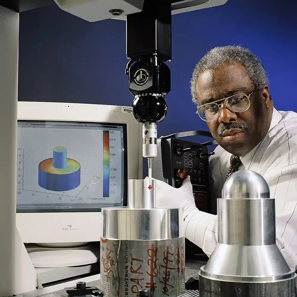
Touch-Trigger vs Scanning Probe Selection for CMM Inspection
A coordinate measuring machine is only as decisive as the probe head mounted on it. The same bridge CMM fitted with a touch-trigger probe or with a scanning head will often return the same nominal diameter on a simple bore, yet differ by an order of magnitude in cycle time, in form error coverage, and in the volume of data the quality system has to store and defend. This page decodes that choice for buyers and inspection planners: what each probing physics actually delivers, which specification numbers separate the two classes, and how to write the decision into an RFQ so vendors quote comparable configurations.
The decision matters at three moments. First, when a first CMM is purchased and the probing package is 10 to 25 percent of the machine price, so mis-specifying it is expensive. Second, when a quality escape exposes roundness or profile errors that a handful of discrete points mathematically could not see. Third, when inspection throughput becomes the constraint between machining output and shipment, and the question shifts from accuracy to parts per shift. Each chapter below ends in a decision action: a tolerance to check, a datasheet line to demand, or an acceptance test to write into the contract.
Touch-trigger probing samples discrete points; scanning holds the stylus on the surface and streams a continuous point cloud. Every other difference between the two, from form error capability to cost of ownership, follows from that single distinction. This page gives the numbers behind it and an ordered decision sequence.
Chapter 1 / 06
Definitions and Where the Probe Selection Question Arises
A touch-trigger probe is a tactile sensor that produces exactly one coordinate point per contact. The machine drives the stylus toward the surface, the tip touches, a trigger fires, the controller freezes the axis positions at that instant, the machine retracts, and one XYZ point enters the record. A scanning probe, by contrast, is a deflectable stylus assembly with internal position sensing that stays in contact with the surface while the machine sweeps the tip along it, so the controller fuses continuous stylus deflection readings with continuous axis readings and emits a dense stream of surface points. In dimensional metrology practice the boundary is exactly this: discrete sampling versus continuous capture. Everything else, including price, follows.
What is actually being decided is easy to state and easy to get wrong. The choice is not "which technology is more accurate," because machine geometry, scales, and environment dominate most tolerance stacks in either case. The choice allocates four resources: machine time per part, coverage of form and profile callouts on the drawing, probe budget including controllers and software, and the qualification labor that every stylus change consumes. A buyer who compares head prices alone, without the scanning controller, the software modules, the qualification sphere, and the change rack, has not compared the same machine.
The question arises in three distinct duty situations, and the answer differs in each. In first-article and PPAP-type work, part counts are small, the feature count is large, and the entire GD&T scheme is verified once: here scanning pays for itself immediately because the incremental cost per additional point is near zero, and a full form characterization of 20 features can take minutes instead of hours. In routine production inspection, a fixed program of 4 to 8 points per feature is repeated every shift on one part number: here a touch-trigger probe is often the correct economic answer, and scanning adds data nobody queries. In form-critical work, where roundness, cylindricity, flatness, or profile tolerances sit in the 2 to 15 um band on ground or turned surfaces, the point count required by the geometry itself pushes the decision to scanning regardless of volume.
A useful way to frame the cost is to separate the machine error term from the probing error term. The machine term, length measurement error over its measuring volume, is fixed the day the CMM is ordered and is shared by both probe classes. The probing term differs: trigger repeatability and pre-travel variation on one side, scanning deflection fidelity on the other. Acceptance testing per the ISO 10360 series separates these terms deliberately, which is why Chapter 6 tells you to demand both numbers in the machine contract rather than a single fused accuracy claim.
Scope note for readers arriving from search: the general CMM buyer page covers machine architecture, bridge versus gantry versus articulated arm, and shop-floor versus lab machines. This page stays one level deeper, on the probe head subsystem: trigger mechanisms, deflection sensing, head indexing, styli, racks, qualification, and the acceptance tests that expose probing performance specifically. Where a probing choice pushes a job off the CMM entirely, toward a vision measuring machine or a laser tracker, Chapter 3 marks that boundary explicitly so the RFQ goes to the right equipment class in the first pass.
Chapter 2 / 06
How Touch-Trigger and Scanning Probing Work
The classic touch-trigger probe is an electromechanical switch built around a kinematic seat. The stylus carrier is spring-loaded against three seating points, each typically a roller-and-ball or cone-and-ball pair, giving six contact constraints. When the stylus tip touches the workpiece and deflects by a few tens of micrometers to a few hundred micrometers, one or two seats break, the trigger circuit opens, and the controller latches the machine coordinates at the trigger instant. The distance the tip traveled after first contact before the trigger fired is the pre-travel. Pre-travel is large and stable; what matters is its variation, because pre-travel variation maps directly into probing error at the tip.
Datasheet single-point repeatability at the stylus tip clusters around 1.0 to 2.5 um for mainstream industrial touch-trigger modules measured as unidirectional spread, while premium kinematic designs quote down to the 0.25 to 0.35 um class. Read the basis line before comparing: a figure quoted as 1 sigma tells a different story than a figure quoted as a maximum range over 100 touches, and the stylus length behind the number changes it further. When a vendor quotes repeatability without the stylus geometry and the statistical basis, the number is not yet a specification, it is marketing.
The systematic signature of a kinematic trigger is directionality. Pre-travel differs slightly depending on the approach direction relative to the seat geometry, which shows up as a lobed error pattern, classically three lobes over a full 360 degree sweep of approach angles. Probes compensate in two layers: the interface stores a calibration matrix that corrects mean pre-travel per direction, and the measurement strategy reduces residual effects by probing features with balanced bidirectional approaches. This is also why a diameter measured with 4 points and one with 16 points can disagree slightly on the same bore: the residual lobing samples differently. Scanning systems do not inherit this signature, because they never leave the surface.
Stylus mechanics set the real limits of the touch-trigger class. A ruby-tipped stylus is a cantilever: longer styli bend more under the same trigger force, heavier tips lower the natural frequency, and both enlarge the qualification matrix the system must build. This is why every module family publishes maximum stylus length and maximum tip mass. Exceed them and repeatability degrades quietly, long before anything visible happens. During qualification, the system touches a calibrated reference sphere in a defined pattern and derives the effective tip center and the bending compensation matrix for that specific stylus; the matrix is only valid for that stylus, at that length, at that temperature.
The throughput arithmetic of discrete probing follows from its duty cycle. Each point costs an approach, a touch, a retract, and a repositioning move; in practice the class delivers roughly one point per second to one point every few seconds once positioning is included. For pure size and location checks this is fine, because a circle fit for diameter needs only a handful of points, and GD&T practice for size commonly uses 4 to 8 points per cross-section. The arithmetic breaks on form, and the numbers make it concrete.
Consider a 50 mm diameter bore. Its circumference is about 157 mm. To report a diameter, 8 points suffice. To report roundness in a way that survives an audit, the sampled point count must exceed twice the highest undulation you claim to evaluate, and roundness filters on dedicated instruments routinely run to 50 undulations per revolution, so defensible roundness needs hundreds of points per layer: at 0.5 mm point spacing that is 315 points per layer, and a cylindricity evaluation might use 4 layers, so 1260 points. At one discrete point per second, that single feature costs 21 minutes of machine time before moves; at one point every 3 seconds it costs an hour. A scanning head running the same circle at 2 mm/s completes each 157 mm layer in about 80 seconds while its internal sensor samples several hundred to over 1,000 points per second, delivering thousands of raw samples per layer that the software then filters to the spacing you specify. That factor of 10 to 40 in effective point rate is the physical core of this entire selection question.
Inside a scanning head, the stylus is mounted on a deflectable carriage with position sensors, and the controller runs a closed loop that keeps deflection inside a target band while the machine axes follow the contour. Two families exist. Active heads carry servo-driven deflection control with internal position feedback, which holds contact force nearly constant across slope changes and sustains higher scanning speeds and acceleration. Passive heads rely on spring compliance and the machine servo to manage deflection, trading speed and force control for mechanical simplicity. Either way, every surface point is computed by combining the deflection reading with axis positions read from the machine's linear encoder scales on each axis, so scanning accuracy is a fusion of head and machine performance, never the head alone. Single-point repeatability for scanning systems is typically quoted sub-micron to about 1 um class at the stylus tip.
Two scanning strategies dominate programs, and the choice shows up in cycle time and data volume. Contour scanning drives the tip along the nominal geometry of a known feature, a circle, cylinder, or 2D profile, at a controlled offset, and suits anything the CAD model already defines. Strip or area scanning sweeps parallel bands across freeform or unknown surfaces, trading density for coverage, and it is the default for reverse verification and defect mapping. In five-axis heads, the head itself rotates to keep the stylus normal to the surface while the machine moves slowly and smoothly, which raises practical scanning speed on complex parts substantially because the machine axes stop doing the fast direction changes.
Attribute
Touch-trigger probing
Scanning probing
Point capture
1 point per contact cycle
Continuous stream while in contact
Effective point rate
1 point per 1 to 4 s incl. moves
Several hundred to over 1,000 points per s
Typical tip repeatability class
1.0 to 2.5 um mainstream, 0.25 to 0.35 um premium
Sub-micron to about 1 um
Points for a defensible roundness on a 50 mm bore
315 per layer, impractical at 1 to 4 s per point
315 per layer at 0.5 mm spacing, about 80 s per layer at 2 mm/s
Form error capability
Size and location only; form is undersampled
Roundness, cylindricity, flatness, profile
Systematic signature
Directional pre-travel variation, 3-lobe class
Deflection nonlinearity, corrected in head firmware
Per stylus and per strategy, matrix stored per tip
Chapter 3 / 06
Probe Head Types and Duty Boundaries
Fixed manual heads are the entry class: a touch-trigger probe screwed onto a rigid joint, indexed by hand between feature clusters, and qualified once. They suit occasional measurement on a shop CMM where machine time is not the constraint and the part mix is small. The moment a program needs repeated re-orientation, the manual head costs more in labor than a motorized head costs in capital.
Motorized indexing heads carry two rotary axes and re-orient the probe under program control, typically in 7.5 degree increments giving 168 repeatable positions across the A and B angle ranges, with head re-positioning repeatability in the sub-micron class on current products. Indexing lets one stylus reach features on five sides of a part without re-clamping the workpiece, which removes fixture changes from the cycle. Motorized heads pair naturally with touch-trigger modules; module-change systems let a job swap stylus clusters automatically and reuse stored qualifications rather than re-qualifying after every swap.
Scanning heads split into the active and passive families described in Chapter 2. The relevant selection fact is not the internal architecture but the duty envelope: scanning assumes the machine can hold the contour. On a worn shop-floor CMM with mediocre axis control, a premium scanning head spends its capability correcting for the machine. Scanning also assumes surface continuity: on interrupted surfaces, keyways, and cross-holes, the head must fly across gaps and re-establish contact, and each gap event costs time and adds uncertainty at the re-contact point.
Five-axis scanning heads combine continuous head rotation with machine motion so the stylus stays near-normal to the surface. On parts with many orientations, this cuts total measurement time dramatically because the fast direction changes happen in the head, not in the machine structure, and machine motion stays slow and smooth, which is also the condition under which machine geometry errors contribute least. The cost is a higher-end controller and a more involved qualification discipline across the head's rotary axes.
Non-contact sensors extend the same machine into regimes styli cannot reach. An industrial camera or a laser-line sensor mounted as a head-attachable module measures soft, thin, or tiny features at low contact force, and a 3D scanner using structured light can capture whole freeform surfaces in the 10 to 50 um accuracy class over mid-size parts, an order of magnitude less accurate than tactile scanning but 10 to 100 times denser per minute. The correct engineering use of optical density plus tactile traceability is a common pairing: scan for coverage, scan again for the few callouts with tight tolerances.
Hybrid configurations are now the mainstream answer for mixed workloads. A motorized head or five-axis head with an automated change rack stores touch-trigger modules, scanning modules, and specialty sensors such as surface finish probes, and switches them inside the program. Racks hold 4 to 12 positions on typical installations; every position needs qualification upkeep. The practical limit of hybridizing is qualification economics: each stored stylus-sensor combination carries a calibration that must be refreshed after temperature shifts and after any collision, so a rack full of rarely used tips is not free.
Know where neither probe class wins, and route those jobs elsewhere before they consume CMM budget. Very large welded or machined structures beyond roughly 2 to 3 m belong on a laser tracker, whose 15 to 60 um class volumetric accuracy over many meters is the correct instrument for the tolerances such parts actually carry. Small flat 2D contours under about 300 mm with tight true-position callouts belong on a vision measuring machine, which images edges at low-micron class accuracy without stylus access problems; the optical comparator remains the shop-floor projection instrument for quick profile checks against a template. Surface texture parameters Ra and Rz are not form error and belong on a surface roughness tester, although scanning heads that accept surface finish probes blur this line usefully. Quick incoming screens, a shaft runout verified with a dial indicator, a height step checked with a height gauge on a surface plate, or a long span sized with a handheld laser distance meter, cost a fraction of CMM time and keep the machine for the callouts that need it.
Inspection duty
Fitted probing choice
Boundary reason
Bore diameter, tolerance 0.05 mm and wider
Touch-trigger, 4 to 8 points per layer
Point count for size is small; scanning adds unqueried data
Roundness 5 um on a 50 mm ground bore
Scanning, 300 to 500 points per layer
Undulation coverage requires hundreds of points per revolution
Cylindricity across a 120 mm deep bore
Scanning, 3 to 5 layers, contour strategy
Multi-layer density plus axial straightness needs a stream
Profile of a surface, tolerance band 0.1 mm, freeform blade
Five-axis scanning, strip strategy
Normal-to-surface tracking across slope changes
Position check on thin sheet features
Vision module or vision measuring machine
Contact force deflects thin material
Deep bore, 6 mm access, 200 mm depth
Long stylus touch-trigger or swiveled scanning stylus
Stylus aspect ratio limits; qualification dominates
Weldment envelope 5 m
Laser tracker
Beyond CMM envelope; tracker accuracy class fits the tolerances
Surface roughness tester or head-mountable finish probe
Texture parameters are not geometric form error
First article, 60 callouts, one part
Scanning program with mixed touch points for datums
Marginal cost per additional point is near zero
Chapter 4 / 06
Key Specification Parameters Decoded
Probe datasheets publish a compact parameter set, and every line hides a basis you must pin down in the RFQ. The table below lists the lines that decide selection, the spread you should expect across current industrial catalogs, and the question each line should make you ask. Treat the ranges as catalog classes for mid-size bridge CMM configurations, not as vendor quotes; your configuration, stylus set, and software shift each number.
Parameter
Touch-trigger typical
Scanning typical
What it controls and what to demand
Single-point repeatability at tip
1.0 to 2.5 um mainstream, 0.25 to 0.35 um premium
0.1 to 1.0 um
Demand the basis: sigma or max range, touch count, stylus length, direction set
Maximum stylus length
50 to 300 mm depending on module
20 to 100 mm typical scanning styli
Longer stylus softens repeatability; ask for the derating statement
Maximum stylus or tip mass
10 to 30 g module dependent
3 to 12 g
Overshoot on direction changes; drives qualification frequency
Approach speed / positioning
5 to 20 mm/s final approach, faster search moves
Scanning speed 0.5 to 20 mm/s, five-axis higher effective rates
Cycle time driver; confirm speeds at which stated accuracy holds
Maximum point rate
1 point per 1 to 4 s effective
200 to 1,000+ points per s
Ask whether the rate is sustained or burst, and at what filtering
Minimum feature access
0.3 to 3 mm bores with small styli
1 to 6 mm
Stylus ball diameter sets the floor and the minimum form radius
A-B indexing angles
7.5 deg steps, 168 positions on motorized heads
Continuous on five-axis heads
Feature reach planning; indexing repeatability sub-micron class
Re-qualification after change
Stored per module on change systems
Stored per tip and strategy
Rack capacity and calibration storage decide real throughput
Repeatability deserves the most aggressive decoding. A single number without a basis cannot be compared across vendors. Insist on the test condition: stylus geometry, approach direction set, number of repeats, whether the figure is a standard deviation or a maximum spread, and the temperature at which it was measured. Then convert it into the number that matters to you: if repeatability is quoted at 50 mm stylus length and your deepest bore needs 150 mm, ask for the quoted repeatability at 150 mm or walk the quote back to a probe that publishes it.
Scanning speed and point spacing must be read as one parameter, not two. Point spacing equals scanning speed divided by sampling rate: 2 mm/s at 400 points per second yields 5 um spacing, which is far denser than most evaluations need, and controllers therefore filter down to the evaluation spacing, typically 0.05 to 0.5 mm. The specification question is not the maximum rate, it is the accuracy class the head holds at the speed your cycle plan assumes, and whether that accuracy is demonstrated by a scanning probing error test on a reference sphere rather than by a repeatability figure at a standstill.
Stylus limits interact with feature access more than any other pair of lines. A 300 mm stylus reaches a counterbore at the bottom of a deep pocket, but its effective mass and compliance make the published repeatability optimistic unless the vendor derates it. A 0.3 mm stylus ball enters a 1 mm hole but cannot characterize form in that hole because the ball radius itself filters the surface. Write your ten worst access cases into the RFQ and make the vendor state the probing performance at those specific geometries; that single move converts a datasheet into a commitment.
Indexing granularity looks like a convenience feature until a specific part defeats it. With 7.5 degree steps, a feature whose normal falls between steps gets a longer stylus, a slower strategy, or a compromise approach angle, each of which costs accuracy or time. Five-axis heads exist precisely because continuous orientation removes that compromise. Audit your part family for approach angles that land near indexing boundaries before choosing a stepped head over a continuous one.
Finally, demand system-level numbers rather than component numbers. The probing dispersion of the machine-plus-head system, tested in the style of ISO 10360-2 with 25 discrete points on a reference sphere, and the scanning probing error of the same system, tested in the style of the ISO 10360 scanning mode and probing system tests, are the two lines that make vendor claims auditable. A repeatability figure for the head alone excludes the machine, the controller latency, and the stylus you will actually use, and therefore excludes most of your risk.
Chapter 5 / 06
Selection Decision Factors and Cost of Ownership
Work the decision in order. The sequence below is deliberately short-circuiting: each step can end the analysis, and buyers who skip steps usually buy scanning for prestige or touch-trigger for price and then pay for the mistake in machine hours.
Sort the drawing package by tolerance and callout type. List every form and profile callout with its tolerance band. If the list is empty or the bands are wide, 0.05 mm class and looser, stop: touch-trigger covers the work, and budget should go to throughput, not density.
Count the points each callout actually needs. Size and position need 4 to 8 points per feature. Roundness needs hundreds per layer; cylindricity multiplies that by layers; profile of a surface needs strip density across the band. If form-required points exceed about 300 per part in total, the scanning case is already economic at current head prices.
Compute required parts per shift against available CMM hours. Discrete programs on a 30-feature machined part commonly run 8 to 15 minutes; scanning the same part runs 3 to 6 minutes. If the takt line needs 60 parts per shift and the discrete program delivers 30, the choice is made by arithmetic, not preference.
Audit feature access. Deepest bore, smallest hole, tightest approach angle, heaviest part rotation. Access problems move you toward motorized indexing, longer styli with derated performance, or five-axis heads, and these decisions change the quote more than the touch-trigger versus scanning label does.
Fix the datum strategy before buying probing. Datums measured with 3 points define an orientation that a dense scan would define differently, and mixed programs must be consistent. A scanning program that measures datum faces with density and features discretely is legitimate; the reverse is usually an audit finding.
Size the software and data layer. Scanning multiplies point counts by 100 to 1,000, and every point becomes storage, backup, and revision liability under retention rules. Confirm the software licenses the scanning modules, the fitting algorithms, and the reporting your customers demand, and that the data plan covers archive growth.
Price the five-year package, not the head. Controllers, racks, qualification tools, spare styli, annual ISO 10360 re-verification, service contracts, and operator training belong in the comparison table. The head is often less than half the probing package.
Check the escape history. If the plant has paid for a warranty claim, a sorting operation, or a customer containment because a form error passed a discrete program, price that event honestly into the scanning column; a single avoided containment on a high-value part commonly pays the delta.
The cost table below uses indicative list-price classes for mid-size bridge CMM probing packages. They are decision-scale numbers, not quotations; your configuration, region, and negotiation move every row.
Cost element
Touch-trigger package
Scanning package
Notes for the comparison
Probe head and interface
8,000 to 40,000 USD class
25,000 to 90,000 USD class
Motorized indexing head at the top of the touch-trigger range
Scanning controller and software
Included or minor module
10,000 to 40,000 USD class
Fitting and form evaluation modules are usually licensed per seat
Change rack and modules
3,000 to 12,000 USD class
5,000 to 20,000 USD class
Capacity 4 to 12 positions; each position needs qualification upkeep
Qualification tools, sphere, styli, first year
1,000 to 5,000 USD
2,000 to 8,000 USD
Scanning styli are more fragile and replaced more often
Annual calibration and ISO 10360 verification
2,000 to 6,000 USD
3,000 to 8,000 USD
Scanning verification adds the scanning probing error test
Qualification labor per shift
5 to 15 min
10 to 30 min
Per tip 30 to 60 s; racks with stored calibrations cut this
Operator training
1 to 2 days
3 to 5 days
Strategy and filtering decisions shift to the programmer
Two comparison traps are worth naming. First, the second-machine trap: when the workload is pure high-volume discrete checking, two touch-trigger CMMs often outperform one scanning CMM at the same spend, because parallel fixtures and programs beat density. Second, the prestige trap: scanning bought for form capability that the drawing never calls out adds qualification labor and data volume with no return. The honest crossover is the drawing package: form callouts at 2 to 15 um tolerances are the scanning customer; everything else negotiates.
Write the RFQ so the answers are comparable. The checklist below is the minimum set of inputs that lets two vendors quote the same machine:
Part list with materials, sizes, and weights, and the three worst access cases with dimensions.
The ten tightest callouts verbatim from the drawings, including all form, orientation, location, and profile symbols with tolerance bands and datum references.
Datum strategy and fixturing intent, including which datums will be probed versus qualified hardware.
Required throughput: parts per shift, shifts per day, and the audit standard your customers impose on retained results.
Environment statement: temperature control class, gradient limits, vibration sources, and part soak practice.
Acceptance tests demanded at commissioning: length measurement error, probing dispersion in the ISO 10360-2 style, scanning probing error in the ISO 10360 scanning and probing system style, all at your stylus configuration.
Probing package scope: head, controller, software modules, rack capacity, qualification tooling, spare styli, and the training days included.
Support terms: response time, loaner head policy, calibration interval, and the price of the annual verification visit.
A final sanity step before signature: benchmark the borderline form callouts against a dedicated roundness tester if you have access to one. Spindle-type roundness instruments reach radial error classes the CMM cannot, roughly 0.02 to 0.1 um, so tolerances tighter than about 2 um on rotationally critical parts belong on the dedicated instrument, with the CMM measuring everything else. Deciding that split before purchase prevents buying CMM capability that physics will not deliver.
Chapter 6 / 06
Field Practice: Acceptance, Qualification, Maintenance
Acceptance is where the probing decision becomes enforceable. The ISO 10360 family separates machine error from probing error so each can be contracted. In the style of ISO 10360-2, length measurement error is verified with calibrated gauge blocks or step gauges measured in several orientations across the volume, while probing dispersion is tested with 25 discrete points on a reference sphere, from which the standard derives a probing dispersion value you can state as an MPE line in the contract. Scanning performance is covered by the scanning measuring mode and probing system tests of the series, associated with ISO 10360-4 and ISO 10360-5, where a scan of a reference sphere or circle yields a scanning probing error driven by form fit. Demand all three numbers, demand them on your stylus configuration, and demand they be demonstrated at commissioning with the report in hand.
For parts whose tolerance stack is close to the machine capability, add uncertainty by workpiece substitution: the ISO/TS 15530-3 approach calibrates a representative workpiece on a reference machine and uses it as the check standard for routine verification of the shop process. This converts an abstract MPE table into a defensible statement about your actual geometry, which is exactly what automotive and aerospace auditors ask to see.
Temperature discipline dominates day-to-day error more than any catalog parameter. The reference temperature for dimensional measurement is 20 C per ISO 1, and probing performance is meaningless if the part is 4 degrees away from it. Practical classes: hold the lab at 20 C plus or minus 0.5 to 1 C, keep gradients below about 0.5 C per hour, and soak parts before measurement; a still-air rule of thumb on the order of 1 hour per 25 mm of steel section is a starting point, to be validated on your part mix. Aluminum soaks faster per unit mass but moves four times further per degree, which cuts both ways. Stylus assemblies are small and equilibrate quickly; the part is what betrays you.
Qualification is the recurring tax on both probe classes. Every stylus tip in service must be qualified against the reference sphere, typically 30 to 60 seconds per tip for touch-trigger and longer for scanning because the deflection matrix needs touches in defined directions. Re-qualify after a stylus change, after a temperature excursion beyond your control band, after any collision however minor, and whenever drift checks on a daily reference feature exceed your control limits. Change racks with stored calibrations reduce but do not eliminate this: stored matrices go stale after head service, so keep a weekly verification touch on a calibrated artifact, for example a ring gauge or a short gauge block stack measured on a routine schedule, and trend the result.
Failure modes arrive in a predictable order. Stylus ball wear shows up first on cast iron and abrasive surfaces, where ruby tips develop flats that bias every subsequent measurement; the countermeasure is rotation-invariant qualification intervals, tip inspection under magnification, and replacement on schedule rather than on failure. Stylus loosening at the thread seat introduces slow drift that daily artifact checks catch. Module seating contamination from coolant mist changes pre-travel and argues for protective caps and clean storage. Head collisions misalign the stylus carrier; the collision detection that protects the head works only if its settings match your actual approach speeds, so review it after every new program. Finally, thermal growth of long styli across a shift is a real error source on large parts, which is why long-stylus programs belong in the best-controlled hours of the lab schedule.
Maintenance contracts should be specified with the machine, not after it. Annual verification against the ISO 10360 acceptance set, with the probing dispersion and scanning probing error tests repeated on your configuration, is the cadence most quality systems expect; tighten to 6 months for tight-tolerance labs. Stock the styli your programs depend on, because a 2-week stylus lead time with no spare is a stopped CMM. Keep the daily artifact checks running between visits: a quick bore or height gauge cross-check on the surface plate and a dial indicator runout check on a held reference part catch machine-level anomalies between formal calibrations at negligible cost.
Documentation closes the loop. Retain acceptance reports, re-verification certificates, qualification logs with stylus serials, drift trend charts, and the software configuration at each audit epoch. Auditors under IATF 16949-style laboratory expectations do not ask whether the probe was accurate; they ask how you know, and when you last checked. The inspection program that answers with dated artifacts instead of vendor claims survives both the audit and the escape investigation, and the difference between the two is procedure, not budget.
FAQ
When is a touch-trigger probe enough for CMM inspection?
When the callouts are size, position, and simple location with tolerances around 0.02 to 0.05 mm or wider, part programs repeat on a fixed schedule, and 4 to 8 points per feature answer the drawing. Production SPC on stable machined parts is the classic case. The moment roundness, cylindricity, or profile tolerances enter the 2 to 15 um band, discrete point counts stop being defensible and the case moves to scanning.
How much does scanning capability add to the price of a CMM?
Plan on the probing package rising by roughly 25 to 60 percent over a comparable touch-trigger configuration, covering the scanning head, its controller, the form evaluation software, and the qualification tooling. Five-axis and hybrid sensor configurations sit above that band. Budget also for higher styli consumption and a longer annual verification, and price those five-year lines into the comparison rather than the head alone.
Does a scanning probe make CMM measurements more accurate?
Not by itself. Machine geometry, scales, and environment dominate length measurement error in both classes. Scanning improves point density, form estimation, and per-point capture consistency, with tip repeatability in the sub-micron to 1 um class, but a tight diameter on an open tolerance measures the same either way. Demand system-level acceptance numbers, the ISO 10360 style probing dispersion and scanning probing error, before crediting any head with accuracy.
Which form errors actually require scanning density?
Roundness, cylindricity, flatness over large faces, and profile of a surface. The rule of thumb is that point count must exceed twice the highest undulation you claim to evaluate, and roundness filters routinely run to 50 undulations per revolution, so a defensible roundness needs hundreds of points per layer. A 50 mm bore at 0.5 mm spacing means 315 points per layer; that is minutes of scanning and untenable as discrete touches.
Can one CMM do both touch-trigger and scanning work?
Yes, and this is now the mainstream configuration for mixed workloads. Motorized heads and five-axis heads accept touch-trigger modules and scanning modules through automated change racks holding 4 to 12 positions, and one program can mix discrete datum touches with scanned features. The cost is qualification upkeep on every stored tip, so size the rack to the stylus set your programs actually call.
What ISO 10360 acceptance numbers should I demand?
Three, measured on your stylus configuration at commissioning: length measurement error over the volume in the ISO 10360-2 style; discrete probing dispersion from 25 points on a reference sphere; and a scanning probing error from the scanning mode and probing system tests associated with ISO 10360-4 and ISO 10360-5. State each as an MPE line in the contract with test conditions, and require re-verification annually.
How do styli and qualification time eat inspection throughput?
Every stylus tip needs 30 to 60 seconds of qualification against the reference sphere, and re-qualification follows every stylus change, collision, and thermal excursion. A 12-tip rack can consume 6 to 12 minutes per shift before any part is measured, and long-stylus configurations take longer. Racks with stored calibrations and disciplined stylus standardization, fewer tip variants, longer runs between changes, recover most of that time.