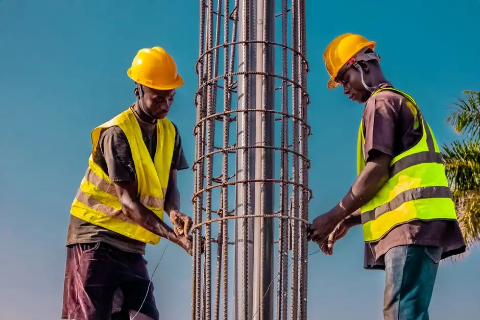
ACI 117 quantifies rebar placement tolerances by member thickness and depth, with cover allowed at ±3/8 in. for members greater than 4 in. and up to 12 in., and ±0.25 in. for typical slabs and walls [S2][S3]. The standard also sets effective-depth tolerances of ±1/2 in. for members 4-12 in. and ±3/8 in. for members over 12 in., and pins the longitudinal location of bends and bar ends at ±2 in. (ACI 318, Section 25.3) [S2].
These limits exist because no fabrication or placement process can replicate design coordinates exactly. ACI 301 requires cast-in-place concrete tolerances, including those for reinforcing-bar fabrication and placement, to comply with ACI 117, and ACI 117's own definition reads: a construction tolerance is a permitted deviation from a specified dimension, location, or quantity [S1]. The licensed design professional (LDP), not the general contractor, owns the tolerance scheme (ACI 117.1R Section 3.2, ASCC Position Statement #18) [S1].
Cover Tolerance: ±3/8 in. for 4-12 in. Members
ACI 117 allows a concrete cover tolerance of ±3/8 in. when member size exceeds 4 in. but does not exceed 12 in. (ACI 318, Section 26.6.2) [S2]. For slabs and walls, rebar cover tolerance tightens to ±0.25 in., and embedded pipe alignment is held within ±1 in. depending on size and function [S3]. Cover is the most field-checked rebar parameter because it is what protects the steel from corrosion, fire, and impact.
Tolerance is not the same as design cover. The design value comes from ACI 318 exposure and fire requirements; ACI 117 only defines how far the as-built cover can deviate from that specified value. Specifying tolerances more restrictive than ACI 117 is discouraged in the SEAofNC technical note, because tighter limits rarely buy extra safety and frequently create field conflicts [S1].
Effective Depth: ±1/2 in. Below 12 in., ±3/8 in. Above
Effective-depth tolerance is set at ±1/2 in. for members over 4 in. and up to 12 in., and ±3/8 in. for members over 12 in. (ACI 117, Section 2.2) [S2]. Effective depth is the structural lever arm between the compression face and the centroid of tension steel, and it appears directly in flexural capacity equations. Lose effective depth, lose moment capacity, in roughly linear proportion for under-reinforced sections.
Special-inspection guidance states that placing rebar 1/2 in. beyond code tolerances can reduce structural strength by as much as 20% if it alters the effective depth of a structural member, because rebar spacing is critical for performance [S2]. The number is member-specific, but the direction of the penalty is consistent: a half-inch misplacement at the tension face of a beam is not a paperwork issue. For fabrication-stage geometry on individual bars, rebar is typically cut to length with a rebar cutter sized to the bar diameter, then bent on a rebar bender before placement, because field correction of a mislocated bar is far more expensive than fabricating to spec.
Bar Spacing, Laps, and the Long-Tail Geometry Items
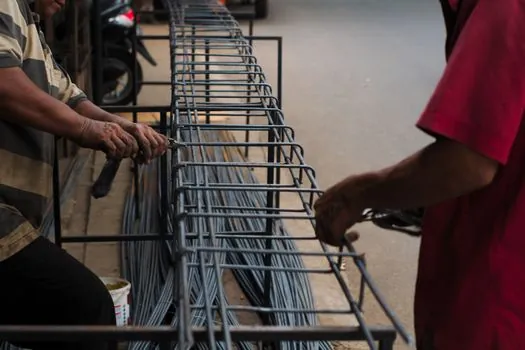
ACI 318 Section 25.2 sets limits on how far apart parallel reinforcing bars can be, with clear spacing in a horizontal layer required to be at least the greatest of one bar diameter, 1 in., or 4/3 times the maximum aggregate size [S2]. Lap and development-length geometry is treated separately from placement tolerance, and the longitudinal location of bends and bar ends is held to ±2 in. under ACI 318 Section 25.3 [S2].
The SEAofNC technical note flags two recurring failure modes. First, confined bars, defined as bars hooked at both ends and trapped by face-cover requirements, provide no field-adjustment slack and may have to be replaced, costing schedule and money [S1]. Second, tolerance stacking, where the cover tolerance, the placement tolerance, the fabrication tolerance (ACI 117 Section 2.1 and CRSI Manual of Standard Practice Chapter 7), the formwork tolerance, and the embed tolerance each consume a slice of the available envelope, can push the as-built geometry outside what the detail will accept [S1][S4]. For long splices and continuity bars, field crews commonly use a rebar coupler at the lap location to remove the lap-length uncertainty from the placement-tolerance problem entirely; the trade-off between threaded and grouted couplers is laid out in Parallel Thread vs Taper Thread Rebar Coupler Installation.
Who the ACI 117 Envelope Is For (and Where It Stops)
ACI 117 applies to cast-in-place concrete structures with nonprestressed steel reinforcing bars, and its scope statement explicitly excludes precast structures, nuclear containments, hydraulic containments, and interfacing systems such as curtain walls [S1]. The tolerances it provides are reference defaults, not project-specific values; the construction documents can always specify tighter or looser limits where the design justifies it (S1, Section 1; S4). The licensed design professional has to set those project limits deliberately, because the contractor is not the tolerance owner (ACI 117.1R Section 3.2) [S1].
It is also worth separating fabrication tolerance from placement tolerance. ACI 117 Section 2.1 (with CRSI Manual Chapter 7) governs cut length, bend angle, and hook geometry, while ACI 117 Section 2.2 governs where the fabricated bar ends up in the form [S1][S4]. A bar can be fabricated to spec and still violate placement tolerance if it is tied in the wrong position, and vice versa. Distinguishing the two is what makes pre-pour inspection productive: a rebar straightener can correct a fabrication deviation, but only a re-tying or re-shimming effort can correct a placement deviation.
Comparison of ACI 117 Placement Limits by Member Type

The table below lines the main ACI 117 / ACI 318 placement criteria up against each other for the cases a field engineer actually has to check. All values are taken directly from the cited guidance and are referenced to the governing ACI section [S2][S3].
Inspections: Periodic, Not Continuous, but No Less Serious
Special inspection of concrete reinforcing steel is required by the International Building Code (IBC) Chapter 17, task #1 of Table 1705.3, but the IBC classifies the inspection as periodic rather than continuous, so the inspector is not on the deck full-time unless the construction documents specifically require it [S2]. The earlier ACI 318 language that mandated inspection of "all" rebar lost that word several code cycles ago, which is what moved project rebar inspection into the periodic bucket [S2].
Periodic does not mean optional. Pre-pour inspection remains the last chance to catch a tolerance violation before concrete buries it, and Strand Co's tolerance guidance treats pre-pour inspection as the single most important checkpoint because post-pour remediation is essentially limited to engineering review and, in severe cases, structural augmentation [S4]. 3D rebar modeling is increasingly used to surface congestion and tolerance-stacking issues before the bar ships to site, but the field check on a member-by-member basis is what closes the loop on ACI 117 compliance [S4]. For a broader look at how mechanical splices interact with these tolerance envelopes, see Structural Epoxy vs Mechanical Fastening: 2026 Load-Bearing Joint Spec Guide.
Limits of the ACI 117 Envelope and Common Failure Modes

ACI 117 does not address tolerance for embedded pipe routing beyond the ±1 in. alignment callout, does not cover post-tensioning tendon profiles, and does not cover splices outside ACI 318's lap and mechanical-splice rules [S3]. SEAofNC's technical note lists the recurring failure modes in detail: cover loss at congested beam-column joints, splice-length shortfall when cover and placement tolerances stack against the available lap, hook conflicts at confined ends, and embed clashes where MEP sleeves and rebar share the same plane [S1].
The general hand tools and placing equipment a crew uses to hold these limits, including rebar tool items such as cover meters, chairs, spacers, and tying patterns, are specified separately from ACI 117 itself, but their accuracy directly bounds what the inspector will measure in the field [S4]. The next trackable signal for engineers on ACI 117 work is the publication status of any post-2015 reapproval and any ACI 318 cycle revision to Sections 25.2, 25.3, or 26.6.2, because those three sections drive bar-spacing, end-location, and cover-tolerance enforcement on the next project.