
Anti-static system design for a cleanroom assembly line is governed by the same triangle every process engineer already knows: cleanliness class, charge-decay path, and ion balance. ISO 14644-1 sets the airborne particle envelope (ISO 5 = 3,520 particles/m³ at ≥0.5 µm, equivalent to FED-STD-209E Class 100) [S1], but the standard is silent on static charge, which is why cleanroom ESD control is bolted on as a parallel engineering discipline.
Static electricity in a cleanroom is generated not only by people and plastics, but also by the FFU airflow itself, with high-velocity air moving across HEPA/ULPA media and ductwork continuously depositing charge on downstream surfaces [S5]. A defensible anti-static layout therefore has to address four physical layers: the floor, the work surface, the personnel grounding path, and the air itself.
Cleanliness Class vs ESD Sensitivity: Choosing the Right Floor
Floor selection is the first cross-coupled decision. ISO 7 lines (PCB assembly, aerospace composites, medical device sub-assembly) and ISO 8 lines (precision manufacturing, plastic injection molding for medical devices, gown rooms) routinely specify vinyl tile loaded with conductive pigment rather than bare epoxy, because a single-pass grounded floor handles both particle shedding and tribocharging [S1][S5]. Surface resistivity targets in this range typically fall between 1×10⁶ and 1×10⁹ Ω/sq, the dissipative band that bleeds charge fast enough to prevent a 50 V human-body event without becoming a live conductor.
For ISO 5 semiconductor and aseptic filling lines, the floor decision is harder: the same vinyl that bleeds charge can shed plasticiser particles, so many fabs use ESD-grade epoxy with a copper-fortified ground grid tied to a single-point ground bar. Either way, the floor must be bonded to the same equipotential bonding network as the workbenches; floating a section of dissipative floor defeats the decay path. A useful cross-reference is the anti-static equipment reference page, which lays out the standard material classes (conductive, dissipative, insulative) that any floor spec must respect.
Personnel Grounding and the Wrist-Strap vs Footwear Question
Personnel is the dominant tribocharge source, and a cleanroom garment change does not eliminate it, only changes the dielectric. The historical failure data is brutal: 50 P-MOS circuits shaken in a plastic bag produced 39 NAND-gate failures, a 78% destruction rate, with no external ESD event required [S5]. Every operator, therefore, needs a verified path to ground with resistance in the 1×10⁶ to 1×10⁸ Ω range; lower and you risk a fault current, higher and the body can still reach kilovolt potentials before bleed-off.
Wrist straps give a continuous, instrumented loop but only work at seated benches, while heel/toe straps on ESD footwear extend coverage to mobile operators on the line. The general decision rule used on most lines I have seen: a continuous wrist-strap monitor is mandatory at any station handling bare dies, Class 3 implantables, or sub-µm lithography parts; a foot-strap plus a daily body-voltage test is acceptable for ISO 7–8 PCB and medical device assembly. The companion Personnel Grounding vs Equipment Grounding reference expands the same logic into a structured decision tree.
Ionisation, Airflow, and the FFU Charge Problem

Ionisers are not optional on a high-airflow cleanroom. FFU-driven cleanrooms move air at speeds high enough to charge the filters themselves, and a charged HEPA face can pin particulates to one side of the array, degrading both cleanliness and pressure balance. The result is that an FFU cleanroom, by construction, generates static where the previous generation of static-control design assumed it would not exist [S5].
Steady-state DC ionisers with auto-balancing (±35 V or tighter) are now standard on ISO 5 lines, while pulsed-DC or AC units are common in ISO 7–8 plastic and PCB assembly where the charge polarity swings with each robotic pick-and-place cycle. A useful product-line anchor is the static-var-generator-style balancing topology family, which uses a feedback loop on the ion current to hold offset within a known window. For very high-throughput lines, the 33 kV long-range eliminator class (built-in field polarity sensing, adaptive ionisation output) is increasingly specified for cross-room neutralisation, and Fraser's July 2024 launch of the Static Clean International product line into the UK and Ireland markets reflects how this segment is consolidating around turnkey ionising guns, particle traps, and medical cleaning stations rather than point-source bars [S3].
Workstation Layout: Where the Ground Loop Breaks
Most field failures I have seen are layout failures, not part failures. A common pattern: an ESD-dissipative mat on a non-conductive laminate bench, with the bench bonded to the building steel through its own mounting bolts and the mat bonded through a separate 1 MΩ resistor, leaving two parallel return paths that can differ by tens of volts during a fast transient. The fix is a single-point ground bar at the workstation, with the mat, bench, shelf, light fixture, and any conveyor segment landed on the same stud, and the stud run back to the facility ground through one and only one path. [S1]
Mobile carts are the second biggest source of latent defects. A cart with a vinyl top, conductive castors, and no drag chain will float at a different potential than the bench, and every time the operator places a tray on the bench you get a micro-discharge. The acceptance test is simple: a portable surface-resistivity meter and a 100 V megohmmeter, then continuity from any point that touches a product to the facility ground with the line running. Failures are almost always a broken bond strap under a sink or a contaminated snap on a wrist cord, not the instruments themselves.
Validation, Monitoring, and Acceptance Criteria
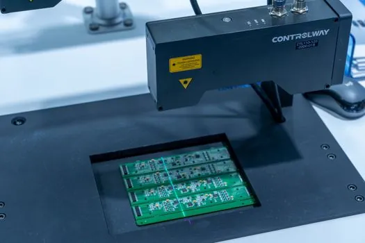
Acceptance testing for an anti-static cleanroom follows a small, well-defined checklist. Floor and bench surface resistivity measured at 10 V with a four-pin probe, against the 1×10⁶ to 1×10⁹ Ω/sq band; body-voltage generation under a walking test, normally held below 100 V peak on a dissipative floor with ESD footwear; ioniser offset and decay time, typically ±35 V and 1 s or better for ISO 5; and a charged-device model pass on the most sensitive part, normally 25 V for Class 0A die or 100 V for Class 1A [S5]. ISO 14644-1 itself does not specify any of these numbers; it only governs the particle envelope, which is why every anti-static line carries a secondary acceptance document, usually keyed to ANSI/ESD S20.20 in the US and IEC 61340-5-1 in Europe.
Re-validation cadence is more important than the initial test. Daily wrist-strap and foot-strap logs, weekly ioniser balance checks, quarterly surface-resistivity surveys, and annual full re-audit, with all of the data tied to the same lot-trace system that follows the cleanroom product. This is also where cleanroom-compatible packaging interacts with the anti-static system: parts are double-bagged in static-shielding film, with the inner bag dissipative and the outer bag conductive, so the product never sits in a Faraday cage without a bleed path before opening [S4].
Comparison: Common Anti-Static Approaches on a Cleanroom Line
The main design choices line up against four decision criteria, and the trade-offs are sharp enough that a single line rarely uses more than two of the options. Option A is dissipative vinyl tile plus heel straps, the lowest-cost path for ISO 7–8 PCB and medical-device assembly, with a typical cost under 50 USD/m² installed and body-voltage held below 100 V but no protection for ungrounded carts. Option B is ESD epoxy with copper grid plus continuous wrist-strap monitoring, the default for ISO 5 semiconductor fabs, with stronger charge decay and a verified personnel loop, but higher installed cost (often 150 to 300 USD/m²) and a hard dependence on a clean ground bus. Option C is full-room ionisation with overhead DC bars plus a dissipative floor, used on flexible PCB and back-end packaging lines where the charge source is the moving film; it handles moving charge sources well, but adds periodic balance maintenance and consumes roughly 30 to 60 W per bar continuously. Option D is hybrid (dissipative floor plus local ionising guns plus wrist straps), which is what most ISO 7 contract manufacturers end up with, and it is also where the Static Clean International product family (ionising guns, particle traps, medical cleaning stations) is positioned as a drop-in fit [S3].
What Goes Wrong, and What the Spec Must Forbid
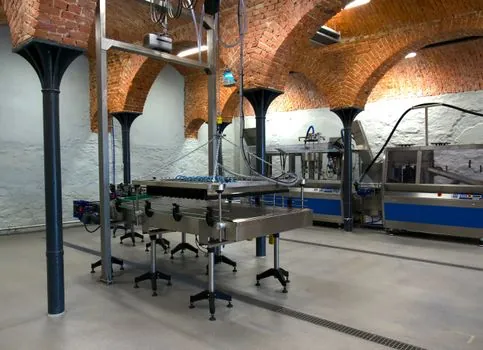
Two failure modes dominate the incident reports. The first is an insulator that someone quietly introduced: a printed label on a dissipative bin, a PU-foam wrist rest, a vinyl chair mat on an ESD floor, all of which can hold tens of kilovolts on a charged surface and then discharge into the next product. The general rule used on disciplined lines is that any material within 30 cm of an exposed product must be either bonded conductive/dissipative or kept outside the EPA boundary. The second failure mode is the lone insulator, usually a hand tool or a fluid bottle, that charges by triboelectric separation and then arcs. The mitigation is a periodic audit with a field-meter and a hard rule that any reading above roughly 100 V on a tool or surface is a stop-the-line finding [S5].
Cleanroom anti-static systems also have to be designed against the more dramatic failure mode. The historical operating-room record shows 36 explosions across 86,000 anaesthetic administrations, of which 21 were attributed to static discharge, a ratio that explains why solvent-handling and flammable-API suites are always grounded, ionised, and operated below the MIE of any dispensed fluid [S5]. A defensible spec, therefore, lists the MIE of the worst-case solvent and the charge-limit of the worst-case operator, and shows they cannot meet at the same time.
Sourcing and Standards Reference
Two cleanroom documents anchor the design: ISO 14644-1 for airborne particles and the FED-STD-209E legacy class numbering still common in US semiconductor and aerospace work [S1]. Two ESD documents anchor the charge control: ANSI/ESD S20.20 in the US and IEC 61340-5-1 in the EU, with the cleanroom-specific guidance usually layered in from the IEST recommended practices. Material and process standards (ASTM D257 for surface resistivity, ASTM F150 for ESD footwear, IEC 61000-4-2 for ESD-immunity testing on equipment) close out the test methods. Vendor product lines now in the cleanroom space include the Fraser/Static Clean International static-elimination range (ionising guns, particle traps, medical cleaning stations) launched into the UK and Ireland market in July 2024 [S3], and a wide catalogue of ESD bins, trays, mats, and grounding hardware routinely called out in cleanroom BOM templates [S2].
Operationally, the spec to track over the next 6 to 12 months is the revision pressure on IEC 61340-5-1 around ioniser balance limits and the slow migration of FED-STD-209E nomenclature into legacy aerospace drawings; both will reshape how cross-references between cleanliness class and ESD class are written into cleanroom-build RFQs. The data point I would watch for in 2026 Q4 is whether the bonded-dissipative-floor-plus-overhead-ioniser pattern, which is now the default on ISO 7 contract-manufacturing lines, expands into the ISO 5 implantable-device suites that have historically run on a wrist-strap-only policy.
Detailed specification references: locking assembly.